1
\$\begingroup\$

enter image description here

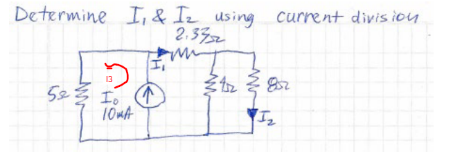
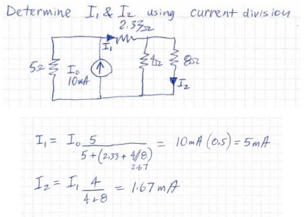
I am working the following example. I understand getting the answers using current division, but I want to get the same answers using mesh (loop) analysis but just can't seem to get it. I want to use mesh analysis to prove that current I3 (we will call this current traveling CCW through the left most loop [5 ohm resistor]). So awesome, we know I1 is 5mA. Using nodal analysis at the point of the top of the current source, we know I1 + I3 = 10mA (current entering must leave current leaving). So, I know I3 is also 5mA. Now I am going to do mesh analysis on the I3 loop.

enter image description here

I get: 10I3 - 10I1 - 5*I3 = 0. =>

5I3 = 10I1. =>

I3 = 2*I1.

This is wrong, I3 does not = 10 mA, it equals 5mA. What am I doing wrong or misunderstanding? How would I do mesh analysis on loop I3 to get the answer of 5mA I am looking for?

Edit for clarity: I'm not asking to do a full mesh analysis of the circuit. Whether I got the value from mesh or current divider, the value should be the same, no? So, let's say I took a shortcut and used current divider to get my value of I1. Whether I use mesh or divider, I should get 5mA. Now, I want to verify I can use either mesh or divider and I should get the same answer. What am I doing wrong in my mesh loop for current I3 drawn, that I can't just get the equation, and plug in my known value of I1 to find my one unknown in the equation, I3? If I am doing something wrong or misunderstanding, that is what I am asking to be clarified.

\$\endgroup\$
12
  • 1
    \$\begingroup\$ Your diagram indicates branch currents I1 and I2. But mesh analysis is done with mesh or loop currents, not branch currents. Please modify your drawing to show which loops your currents are defined on. \$\endgroup\$
    – The Photon
    Commented Dec 7 at 17:33
  • \$\begingroup\$ @ThePhoton I'm not sure that's necessary. The only current that matters in the case of me trying to use mesh to get I3 is I1. The only thing I would add is I1 would be a clockwise loop in the direction already shown. This is the solution provided. Given I know from the solution I1 is 5mA, can I not just use that information using mesh analysis to get I3? \$\endgroup\$
    – RiFF RAFF
    Commented Dec 7 at 17:45
  • \$\begingroup\$ Because "using the results from the current divider method" is not part of mesh analysis. Mesh analysis is a specific algorithm. If you do some other method first and use that as part of the solution, then you're not doing mesh analysis. \$\endgroup\$
    – The Photon
    Commented Dec 7 at 17:46
  • \$\begingroup\$ @ThePhoton Either method should produce the same answer, no? I already know I1, so using that information I have, I can see I am not doing something correctly in my mesh analysis. It should be as simple as getting the correct I3 mesh analysis equation and then I can plug in I1 to get I3, since I already know I1. I am not able to do so, so I am doing something incorrect and am trying to understand where my error is? \$\endgroup\$
    – RiFF RAFF
    Commented Dec 7 at 17:50
  • \$\begingroup\$ Relabel the loops as Ia, Ib, and Ic. I1 is part of two loops. \$\endgroup\$
    – vir
    Commented Dec 7 at 18:00

1 Answer 1

0
\$\begingroup\$

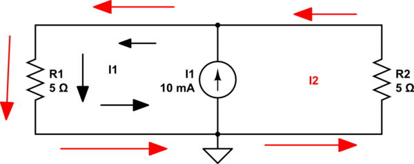
You have only a current source and the Mesh analysis does not like a current source. But we can try to get over it. We can do this if we going to use only one mesh current through the current source.

So I picked this

schematic

simulate this circuit – Schematic created using CircuitLab

And due to the fact that in mesh one we have a constant current source, we know that:

\$I_1 = 10mA\$

Thus the equation for \$I_2\$ mesh will look like this:

\$I_2R_2 + (I_2 + I_1)R_1 = 0\$

\$I_2 R_2 + I_2 R_1 + I_1R_1 = 0\$

\$ 2 I_2 R_2 + I_1R_1 = 0\$

And we have:

\$I_2 = - \frac{I_1 R_1}{2 R_2} = -\frac{50mV}{10\Omega} = -5mA\$

And the \$R_1\$ resistor current will be the sum of currents:

\$I_{R_1} = I_1 + I_2 = 10mA + (-5mA) = 5mA\$

This minus sign in the result indicates that \$I_2\$ in the real circuit is flowing in the opposite direction to the direction that I assumed at the beginning

\$\endgroup\$
2
  • \$\begingroup\$ May I ask why you went around the entire circuit instead of the two loops? We could still arrive at the same answer with two loops equations right? \$\endgroup\$
    – RiFF RAFF
    Commented Dec 7 at 18:19
  • \$\begingroup\$ We need to do this because we have only a current source in your circuit and the mesh analysis is based on Kirchhoff's voltage law. And we don't know the voltage drop across the current source. Therefore, in order to avoid an additional unknown and obtain the correct solution in such a situation, only one mesh current can "pass" through the current source. And this is why I went around the entire circuit instead of the two loops. Take a look at this example electronics.stackexchange.com/questions/546218/… \$\endgroup\$
    – G36
    Commented Dec 7 at 18:26

Your Answer

By clicking “Post Your Answer”, you agree to our terms of service and acknowledge you have read our privacy policy.

Not the answer you're looking for? Browse other questions tagged or ask your own question.