2
\$\begingroup\$

I'm trying to understand the readings I am receiving from the analog to digital converter (ADC).

I am using an integrated uIceblue2 microcontroller. The microcontroller in the circuit is a 18F4550. In the manual of the uIceblue2 microcontroller it says the an analog range from 0 to 3.3v +/-0.8V. It is a 10 bit ADC.

Page 16 of the manual shows the specifications for the analog voltage http://www.saelig.com/supplier/emxys/EMN0210_WE_uIceBlue2_Getting_Started.pdf

EDIT: I realized that I wasn't reading my ADRESH. So when I received 1V, my ADC readings ware 1070 or 1090.

Below are some readings I'm getting from the ADC when I apply a given voltage to the analog input. I am using Docklight to read my results in decimal. I receive to outputs for each result, which I believe coordinate to the ADRESH and the ADRESL. The first group of three digits is the ADRESH and the second group of digits is the ADRESL.

  • 0.055V -> 000 020 to 000 031
  • 1V -> 001 070 to 001 090
  • 2V -> 002 139 to 002 160
  • 3.3V -> 003 255
  • 3.4V -> 003 255
  • 3.5V -> 003 255

My questions are:

  1. Why is there so much variability in the range of the voltage? I thought that 10 bit resolution was quite high and there for the numbers should be constant. For example, I would expect to get a fixed reading of 90 in a row, or a variation of at most 1 in the value, between 89 to 91.

  2. I'm using the following formula to convert the reading back to the voltage, but I don't think it is correct for calculating the voltage from ADC reading.

  3. Is it possible it is already converting to volts?

  4. Should I post my code?

$$Input\,Voltage = Digital\,Reading \times \frac{Voltage\,Range}{Number\,of\,Bits}$$

Could someone please guide me to the correct formula?

\$\endgroup\$
2
  • \$\begingroup\$ How good is your reference voltage? Are you giving enough time for the given resolution? Are you giving it too much time, such that the S+H circuit leaks too much? \$\endgroup\$ Commented Mar 17, 2014 at 19:23
  • \$\begingroup\$ How do I know how much time I'm suppose to give it? Is there a formula or is it trial and error? \$\endgroup\$ Commented Mar 17, 2014 at 19:34

3 Answers 3

3
\$\begingroup\$

The correct formula is \$V_{IN} = \$\$D \cdot V_{REF}\over 2^{NBITS}\$ where D is the digital value. NBITS is 10, so the denominator is 1024. That's assuming Vref(-) is 0V.

If the reference is 3.3V/0V you'd expect a 1V input to produce a digital word of 310 base 10, so something is seriously wrong. I suggest you carefully read the reference manual chapter on the 10-bit ADC as linked here. The data sheet is generally sketchy in the operation of many things.

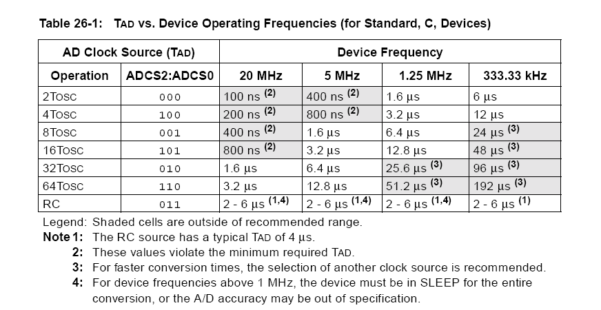
As @Ignatio Vasquez-Abrams points out, adequate \$T_{AD}\$ is very important.

enter image description here

\$\endgroup\$
6
  • \$\begingroup\$ Thank for the response. I don't think I'm using the right values, at 3.3 volts it maxes out at 255. I uploaded the integrated board manual, page 16 outlines my values. \$\endgroup\$ Commented Mar 17, 2014 at 19:44
  • \$\begingroup\$ That is approximately the right answer if you use only the most significant 8 bits. 310/4 = 77.5 and you got 70-90. That part of your problem is firmware-related. \$\endgroup\$ Commented Mar 17, 2014 at 19:46
  • \$\begingroup\$ I realized I wasn't reading my ADRESH, so my values were actually 1070-or 1090. I'm assuming that is directly in volts, however, it is still off from the value. I know it is directly in volts, because as soon as I went to 2 volts, the number went to 2133. \$\endgroup\$ Commented Mar 17, 2014 at 20:01
  • 1
    \$\begingroup\$ 2133 is a somewhat unlikely output from a 10-bit ADC \$\endgroup\$ Commented Mar 17, 2014 at 20:39
  • \$\begingroup\$ PIC ADC's sometimes default to 8 bits unless set to 10-bits \$\endgroup\$ Commented Mar 17, 2014 at 22:31
2
\$\begingroup\$

The ADC numbers you are giving don't make sense - it is a 10 bit ADC - why should a converted number be greater than 1024? You say that with 1V you get 1070 OR 1090. Well, neither are valid numbers and it sounds like 1V gives either 1070 OR 1090 and no value in between.

It should be about 310 so you are definitely doing something wrong in your code but what?

I'm aware this isn't a definitive answer.

\$\endgroup\$
5
  • \$\begingroup\$ Could be a left-justified 10 bit \$\endgroup\$ Commented Mar 17, 2014 at 22:28
  • \$\begingroup\$ I use docklight to receive my results. I get two results for each voltage reading. My impression is the first set of digits is the ADRESH and the second set of digits is ADRESL. For example, when my input voltage was 1 volt. On docklight, I saw the result, 001 090 or 001 073 or 001 078 or 001 086. When I set it to 2 volts. The output was 002 133 or 002 145 or 002 156 etc. \$\endgroup\$ Commented Mar 18, 2014 at 18:15
  • \$\begingroup\$ @user3385015 - the numbers don't stack up dude. Lets say 1V = 1080 (averaged), then I'd expect 2V to be 2160 but it looks a tad light on the numbers. I can't explain why. It's just an observation that things aint what they should be either numerically or linearly. The "range" of numbers for 1V represents maybe +/-1% is also a little high so I guess you should check how you feed volts into the ADC. \$\endgroup\$
    – Andy aka
    Commented Mar 18, 2014 at 18:21
  • \$\begingroup\$ It is 2160 at 2 volts or relatively close. At 3.3 volts it maxes out 003 255. Any higher and it repeats the same thing. Should I post my code? \$\endgroup\$ Commented Mar 18, 2014 at 18:31
  • \$\begingroup\$ I'm not a code man but if you post the circuit how you connect signals into the PIC (aka bluetooth thing) then I might be able to tell you why there are discrepancies and non-linearities. \$\endgroup\$
    – Andy aka
    Commented Mar 18, 2014 at 18:35
1
\$\begingroup\$

One thing that can cause a 10-bit PIC ADC to return results above 1023 is if the conversion is set for a left-justified result. That is bit 7 in the ADCCON2 register is set to zero as per page 231 on the PIC18F4550 Datasheet. To see if that's the case you could try something like the following code that I used in something recently:

    ADCON2=0xBE;  // Slowest conversion time, right justified
\$\endgroup\$

Your Answer

By clicking “Post Your Answer”, you agree to our terms of service and acknowledge you have read our privacy policy.

Not the answer you're looking for? Browse other questions tagged or ask your own question.