0
\$\begingroup\$

I want to make a circuit that turns on and off the light (LED) of a given time (eg. on 9 pm and off 6 am). I also want it to be adjustable.

My idea about the design: I will be using an ATX computer power supply and 3 w LEDs. Control circuit is connected to +3.3 V or +5 V line for voltage conveniency. This part of the circuit will be responsible of opening the relay (switching on the light) at a given time of day and close it at a different time. It have to be adjustable, so I can change time settings.

The LEDs I'll be using is a cool white LED and a warm one, connected in groups like in drawing (one group being the same LED part).

Since the voltage of the LEDs is varying from 2-3 V I want to put 3-4 LEDs in serial, but I need to lower the voltage somehow (and regulate current?), because +12 V is too much.

(Cooling and heat sinks is no problem, I'll just connect fans to the +12V line and add a resistor.)

Summary:

  1. Since the PSU is a switched-mode PSU, is the linear regulator not needed? How can I connect these LEDs in very safe and efficient way?

  2. I don't think NE555 is the right IC for this project. The best thing would probably be to buy a micro controller (àla Arduino) and program it (I'd have to read up on that). Or do you have an idea of how I can make the timer circuit?

  3. Should I use the Panasonic TX-S reed relay? I've also looked at TI TS5A3157, but I don't think that is what I need (The TI is an analog switch).

Archived: Old, messy design drawing, newest drawing below:
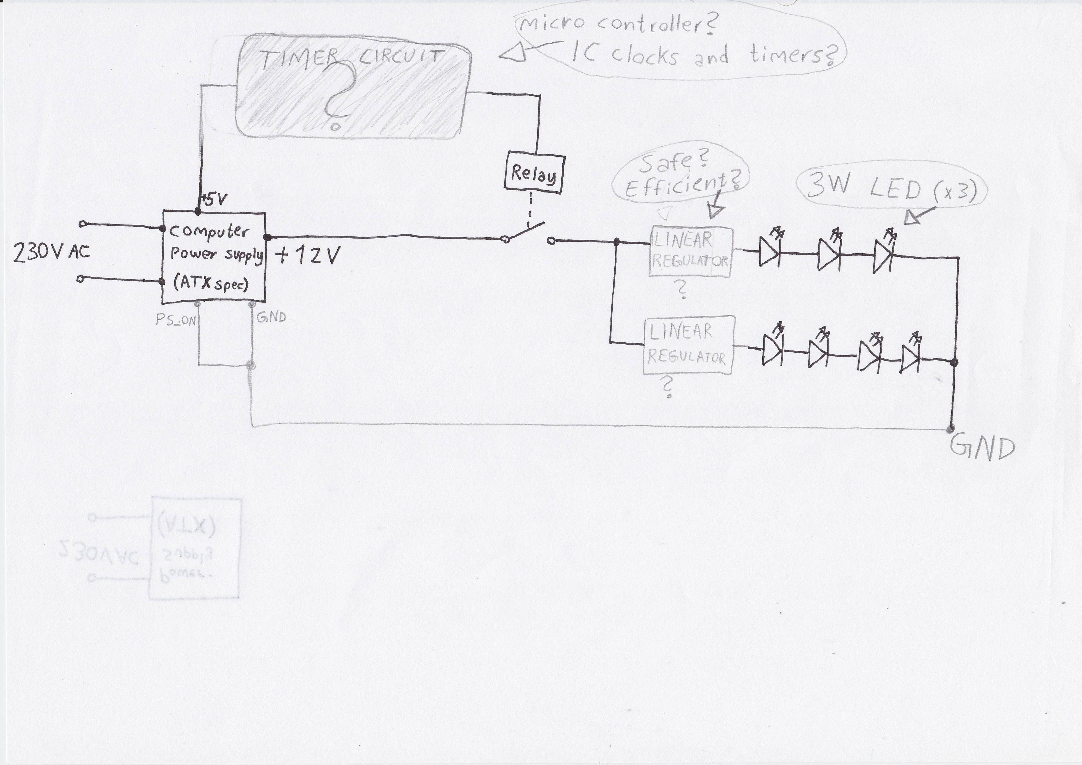
Design drawing

\$\endgroup\$
3
  • 1
    \$\begingroup\$ Too many questions - single questions are required. \$\endgroup\$ Commented Jul 25, 2014 at 19:27
  • \$\begingroup\$ @NeddThehead, we'll probably get down voted for too many comments. :^) I'm new too. But I meant using the micro for the counting. There's probably some clock type modules on spark fun or adafruit. So think 1 second pulses from some clock into a micro, micro does the day/ hour counting, then how do you get the micro to control your LEDs. And finally how to power your leds. Fun project, you'll learn a lot! \$\endgroup\$ Commented Jul 25, 2014 at 21:01
  • \$\begingroup\$ Thanks for the help. :) Question is now totally rewritten. I think I'll use a micro controller. Another approach being a clock/IC and some flip flops/latch which somehow will output high or low to the relay. Not sure how. \$\endgroup\$ Commented Jul 25, 2014 at 21:38

2 Answers 2

1
\$\begingroup\$

The ATX power supply sounds good. You won't need regulators for the LEDs. The ATX power supply should be good enough. However, you will need current limiting resistors. As for the timing circuit, I believe you have overthought it. I would simply use a plug in timer like that of the local hardware store. For example:

http://www.amazon.com/Best-Sellers-Home-Improvement-Plug-Timers/zgbs/hi/6291363011.

For about $10, you can set the on time and off time. All you have to do is plug the power supply into the timer and the timer into the mains.

Better yet, I would look at getting a 12V wall wart power supply for the lights. The ATX is probably cheaper if you have one lying around, but the wall wart would be much more compact.

\$\endgroup\$
5
  • \$\begingroup\$ I'm mostly doing this to learn making circuits like that, I don't want plug-and-play solutions. :) If I just wanted automated lights I'd buy LED bulbs and "mains" timer. And Wall marts PSUs have poor quality and efficiency. Thanks for the current limiting heads-up. What's more efficient of resistor or linear regulator? And is a normal resistor the same as a current limiting resistor? I tried googling it. :/ \$\endgroup\$ Commented Jul 26, 2014 at 18:48
  • \$\begingroup\$ What I think I've learned: I know my PSU is switched-mode type, but it doesn't matter because the voltage is too high. Therefore I still need a voltage/current limiter. I've also read that a swtiching-regulator is much more efficient than both linear regulator and resistors because it takes chunks of power and outputs it, in a rate according to the set/needed current. And that must mean that to get it the most efficient you should instead use/make a custom switching regulator with the right voltage. It would directly convert AC to the right DC voltage and current. Correct me if I'm wrong. :) \$\endgroup\$ Commented Jul 26, 2014 at 19:19
  • \$\begingroup\$ A linear regulator is essentially a resistor that changes its resistance based on feedback from circuit. It's not really more efficient, but the output voltage is more regulated. And yes, a "current limiting" resistor is just a term used to indicate what the resistor is doing. Finally, making your own power supply would be a good option. You would know exactly how efficient it is, and it could potentially be the most compact, convenient solution. However, you must exercise great caution when working with mains voltages.Look in the 317 datasheet for how to design a current regulator as well. \$\endgroup\$ Commented Jul 26, 2014 at 19:25
  • \$\begingroup\$ Thx! Been reading more. I think I'll first of all use Arduino+reed relay and resistors/linear regulators (price dependant). Then, when I've mastered this I'll move on to bigger things. Is it appropriate to post my designs as answers (A) and wait for feedback (quality proof), or should I expand first post (Q)? At the end I want to be able to make this design with my own switched regulator, micro controller, reed relay and of course LEDs. :) \$\endgroup\$ Commented Jul 26, 2014 at 20:36
  • \$\begingroup\$ Neither, really. The format of this site is to post specific questions. We'd be happy to help with a particular issue with your design, but this site isn't set up to guide you through your design. Check out the Help if you are still unsure. electronics.stackexchange.com/help/on-topic \$\endgroup\$ Commented Jul 27, 2014 at 1:17
0
\$\begingroup\$

Nice update, I'll leave the micro timer part of it to others. It depends a bit on what you want to do. I like the relay. (simple) For the LED drive you really want to drive the leds with a current source. The easiest way (for me) to do that is with an LM317 used as a current source. (If you can't find a schematic for that I can post something.)

\$\endgroup\$
8
  • \$\begingroup\$ Thanks! I thought that this power supply was a "current source" itself, as it is a switched-mode PSU (maybe I misunderstood it). But I either way need to lower the voltage. The LM317 looks great for this use. :) Then I'll add those to the list. I'll get back to this tomorrow. \$\endgroup\$ Commented Jul 25, 2014 at 21:48
  • \$\begingroup\$ Nice part indeed. :) But my power supply is a current source for that exact voltage since it's a switched-mode type, or is it not? And a regular (linear?) power supply is not a current source? \$\endgroup\$ Commented Jul 26, 2014 at 20:41
  • \$\begingroup\$ That's what I thought, but when this "current source" and non-linear current characteristics came about I kinda got a bit confused. I always thought that no matter what, you couldn't change the current itself, just voltage, which then directly affected current. "Current limitating" and "current source" is really confusing. I think I'll ask this in it's own question. \$\endgroup\$ Commented Jul 27, 2014 at 14:09
  • \$\begingroup\$ Well a current source keeps the current constant for any load. (up to it maximum voltage which is called the compliance voltage of the current source, the converse of the maximum current that a voltage source can output.) A current source is "happiest" when it's driving a small impedance, and a voltage source is "happiest" driving a large impedance. \$\endgroup\$ Commented Jul 27, 2014 at 14:17
  • \$\begingroup\$ So if I understand it right there will always be a circuit compensating for the voltage and current changes that must accur, because neither of them can be truly constant while the other is variable? Something is just making an output thats constant in both voltage and current? Eg. voltage always changes with current and resistance according to Kirchhoff's laws (except eg. AC circuits)? Why is it even called a current source if the voltage of the output also must be constant to deliver/draw that current? Sorry for all the questions, but I think I'm confusing myself with these questions. \$\endgroup\$ Commented Jul 27, 2014 at 14:27

Your Answer

By clicking “Post Your Answer”, you agree to our terms of service and acknowledge you have read our privacy policy.

Not the answer you're looking for? Browse other questions tagged or ask your own question.