1
\$\begingroup\$

I have a circuit with a rotary switch (1 pole, 6 positions).

Instead of turning this switch by hand, I would like to control it via a computer. Are there any components that can do this? They would receive commands and then switch their relay between several positions accordingly? If so, what are they called?

\$\endgroup\$
9
  • \$\begingroup\$ what is the rotary switch switching? \$\endgroup\$ Commented Aug 28, 2014 at 14:44
  • 1
    \$\begingroup\$ i.e. what sort of signal or power, volts and current. \$\endgroup\$
    – Andy aka
    Commented Aug 28, 2014 at 14:48
  • \$\begingroup\$ DC voltage 0-99V, low current (<10mA) \$\endgroup\$ Commented Aug 28, 2014 at 14:49
  • \$\begingroup\$ This could possibly be replaced by MOSFETs, if it's just a signaling system instead of carrying actual power. But we'd need to know more about the circuit. \$\endgroup\$ Commented Aug 28, 2014 at 14:54
  • 2
    \$\begingroup\$ Six single-pole single-throw normally-open (reed) relays would be an option. \$\endgroup\$ Commented Aug 28, 2014 at 15:00

4 Answers 4

4
\$\begingroup\$

You can get a reed relay, such as this one, with contacts rated at 200 VDC @ 500 mA, and a nominal coil voltage of 5v. The datasheet is here.

The advantage of a relay over a transistor solution is it would provide total isolation. Also the easiest way of integrating into your current system, just wire the relay contacts across your switch contacts.

Since you are switching a fairly low current, you might want to use a relay with two Form A contacts and wire them in parallel. This relay is identical to the one above except it is DPST (and costs about twice as much).

\$\endgroup\$
2
  • \$\begingroup\$ Excellent idea! Unfortunately - from the data sheet - that particular relay can only hot-switch 60VDC, max, for any current up to 350mA through the nickel-silver contacts. \$\endgroup\$
    – EM Fields
    Commented Aug 28, 2014 at 19:38
  • \$\begingroup\$ @EMFields Thanks for pointing that out. I have edited my answer for a different relay that has a switching current of 500 mA (carry current of 1A) and a peak voltage rating of 200V. Better specs, and cheaper. \$\endgroup\$
    – tcrosley
    Commented Aug 28, 2014 at 19:58
4
\$\begingroup\$

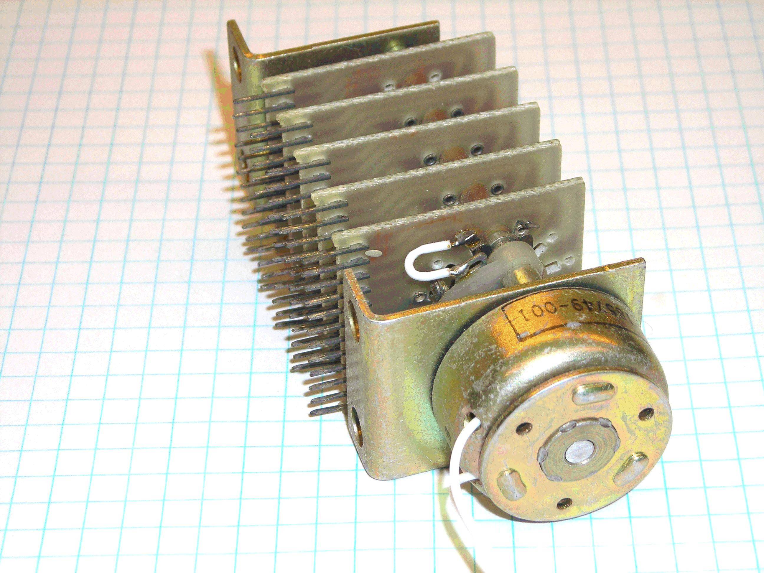
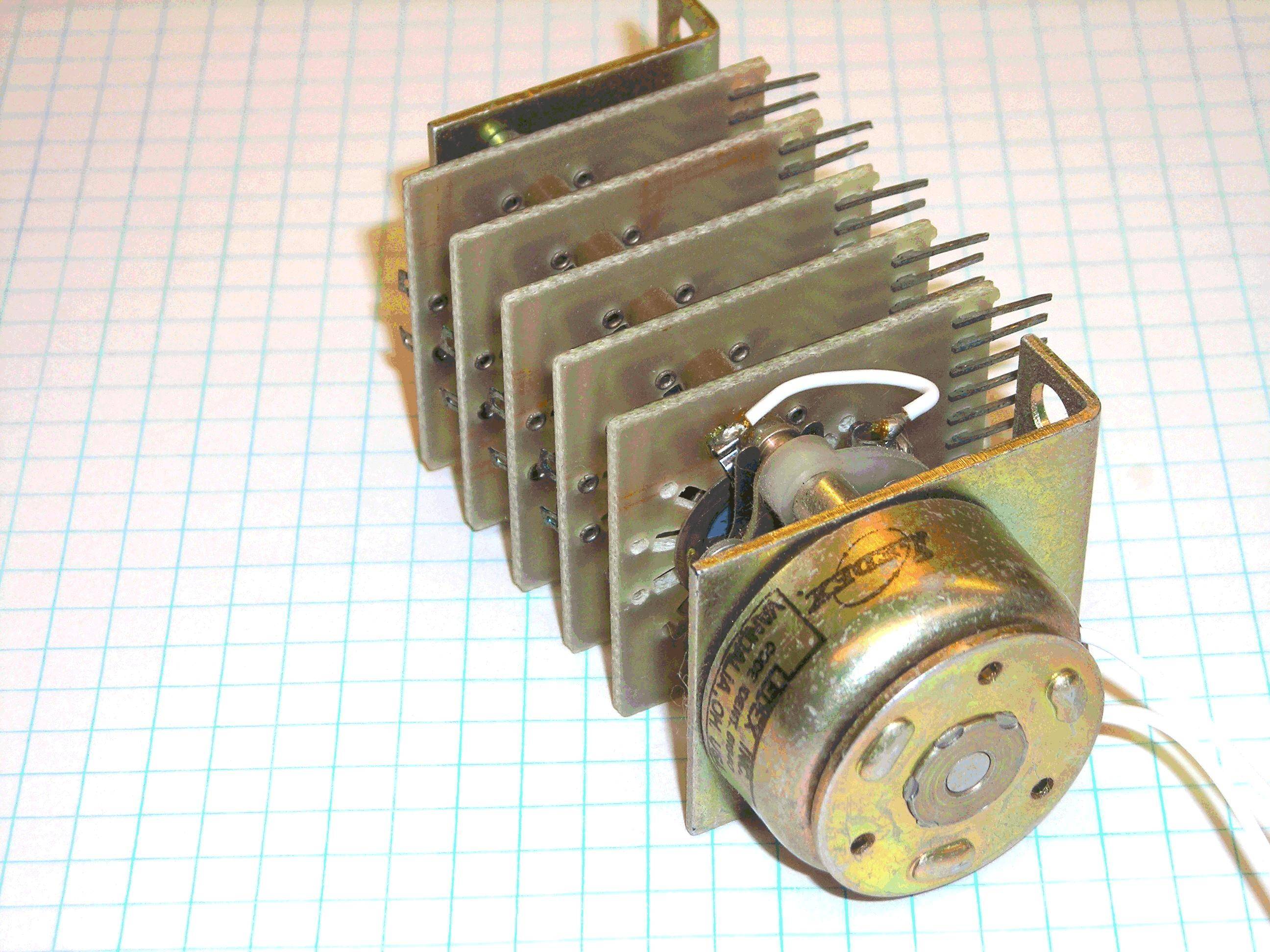
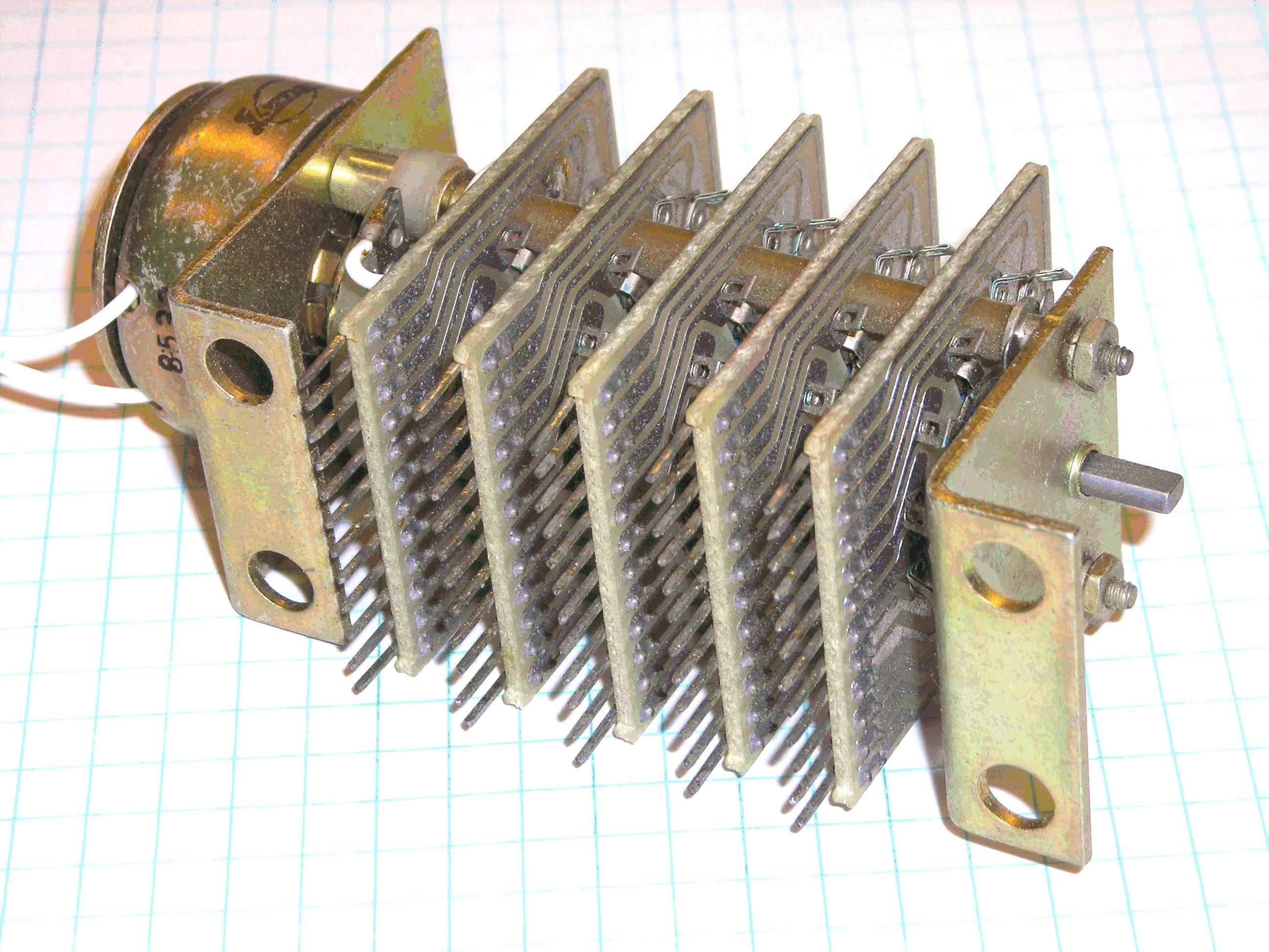
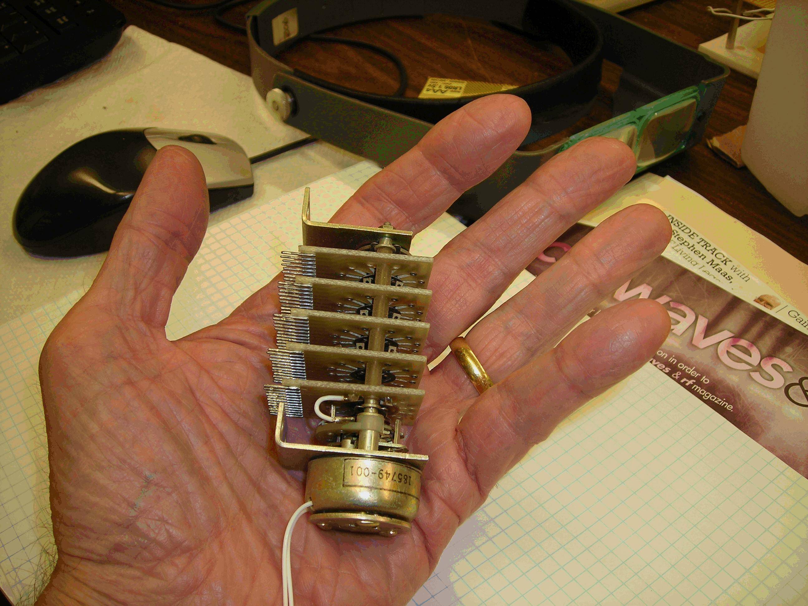
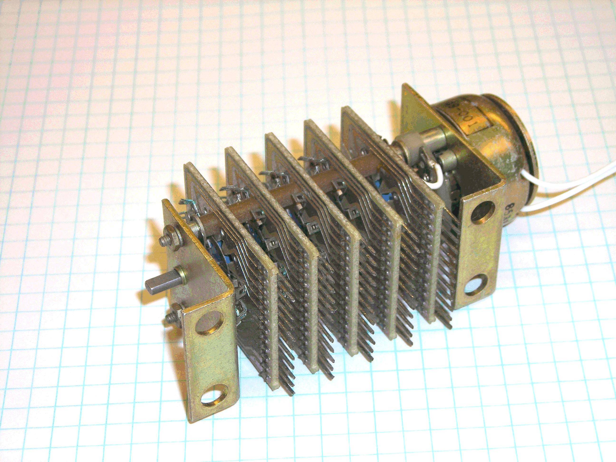
They're called "rotary stepping switches" and one version is made by coupling a rotary solenoid to a rotary switch, as shown below.

A bit overkill for your application, which can be easily handled by six relays driven individually by separate MCU I/Os, or driven by something like a 74HC138 with omly three IOs required from the MCU.

enter image description here enter image description here enter image description here enter image description here enter image description here

\$\endgroup\$
1
  • \$\begingroup\$ Interesting! I wish someone would make something like this but about 10x smaller. I could see pro-audio gear and vacuum tube stuff use such a part in place of all of the various potentiometers and switches and then you can remotely control your gear! For example, a tiny motor with a worm or pinion driving a gear that has the switch wiper on one side and grey-code wiper on the other side and then sandwich that between two PCBs w/ necessary traces. PCB also has h-bridge motor driver and circuitry to take a 4 bit code and drive the motor to one of 16 positions. Someone manufacture that please. \$\endgroup\$
    – squarewav
    Commented Aug 29, 2014 at 4:07
3
\$\begingroup\$

I have seen stepper switches which are solenoid-controlled rotary switches. You pulse the solenoid for a specified time at a specified voltage, and the switch advances to the next position. However, such things are physically large, not easily and commonly available, and quite expensive.

The right solution is to step back two logical layers and define what you really want to accomplish, and leave any supposed solution like a rotary switch out of it.

Apparently you want to switch 100 V at 10 mA to 6 different feeds. That should be doable using transistors for much lower cost, much lower size, and much higher reliability. To recommend the best architecture, you need to tell us more about what is being switched on and off. For example, is it OK to switch the grounds, or must the power be switched?

At worst, a few FETs or BJTs as high side switches should work here. These can be controlled from a microcontroller, which can implement the sequencing logic to emulate a rotary switch, if that even matters. Basically, the micro has individual control over each of the 6 switches, and the rest is firmare logic.

Added

I see using relays is a popular answer. That would certainly work, but relays have downsides too. The way to decide whether relays or transistors are more appropriate is whether you need isolation or not, which you haven't told us. If you need isolation between these power feeds that are being switched and the control logic that decides what needs to be switched when, then I'd use relays. If everything has a common ground then I'd use transistors.

Transistors will be smaller, cheaper, and last much longer than relays, so I'd use the relays only if the the extra isolation they provide was a benefit.

\$\endgroup\$
6
  • \$\begingroup\$ Thanks Olin, my question was not clear, I agree that we need to leave the rotary switch out of the equation. I want to switch a 100V/10mA power between 6 different feeds. Currently, both the ground and power lines are switched (the rotary switch that I use is in fact a 2 pole/6 pos switch) \$\endgroup\$ Commented Aug 28, 2014 at 15:17
  • \$\begingroup\$ Whoever downvoted this: Please explain what you think is wrong, misleading, or badly written. \$\endgroup\$ Commented Aug 28, 2014 at 17:24
  • 1
    \$\begingroup\$ I didn't downvote you, but I suggest your generally abrasive and overbearing attitude had something to do with it. For example, your: "The right solution is to step back two logical layers and define what you really want to accomplish, and leave any supposed solution like a rotary switch out of it." is insulting in that it casts the OP in the role of a dunce for having the temerity to suggest that an electrically controlled rotary switch might be a viable option and that you're the keeper of the keys to the kingdom. \$\endgroup\$
    – EM Fields
    Commented Aug 28, 2014 at 19:53
  • 3
    \$\begingroup\$ Olin: What you suggested wasn't a solution, it was an approach to a solution, and what you took umbrage at was that the OP took time out of his life to study the problem, come up with a tentative solution, and then come here to ask for verification or help with finding a better solution, exactly what this site is supposed to be for, AIUI. As far as my liking or disliking the "message" goes, you seem to be confused in that I wasn't responding to the technical part of your post, per se, but to your query as to why you were downvoted. In simpler terms, then, because you're a bully. \$\endgroup\$
    – EM Fields
    Commented Aug 28, 2014 at 21:15
  • 1
    \$\begingroup\$ Again, I wasn't responding to the technical part of your post, but rather to the question you asked about why you had been downvoted \$\endgroup\$
    – EM Fields
    Commented Aug 28, 2014 at 22:16
0
\$\begingroup\$

Unfortunately there is no such thing as an electronically controlled stepped switch. I recently tried to find exactly what you describe. Old telephone network "stepper switches" technically fit the description but in practice they are almost certainly not applicable to doing anything but routing telephone calls. The nearest practical alternative to a physical rotary switch that can be electronically controlled, would be a series of individual electronically controlled switches wired in an appropriate way. But the type of switch that must be used depends greatly on what precisely is being switched. If it is a current to power something like a motor, a series of solid state relays might be sufficient (or one of those old-school RC car speed controllers connected to a servo). If you are switching something like audio or small signals, you could use regular relays. Relay controlled stepped attenuators are popular DIY projects. But they are large, suffer from switching noises, expensive and generally crude. Depending on the load you might find an "analog switch" that is suitable. For example, Analog Deviecs make a number of analog switches that are relatively high performance. They have low on resistance, low on resistance flatness and support +-15V. Unfortunately, analog switches and solid state relays (analog switches are really just speciality solid state relays) have high junction capacitance that can be 100's of pF. It seems the lower the on resistance, the higher the capacitance. That might not sound like a lot but if you have 6 junctions with 100p capacitance on both the source and drain, that can easily alter audio flowing through the switch unless the load is like 1k. You would have to design the circuit around the switch. OTOH, if you're just trying to control some LEDs or something of that nature, then solid state relays would be overkill. You could just use regular transistors. If you care to elaborate on precisely what is being switched, you will probably get better answers.

\$\endgroup\$
2
  • \$\begingroup\$ Actually there is such a thing as a electronically controlled stepped switch. The last one I saw was 40 years ago, weighed a pound or so, and required 110 VAC to drive the solenoid to step the switch, but these things do exist. I've personally held one in my hand. \$\endgroup\$ Commented Aug 28, 2014 at 21:41
  • 1
    \$\begingroup\$ ioplex: See my post. \$\endgroup\$
    – EM Fields
    Commented Aug 28, 2014 at 23:37

Your Answer

By clicking “Post Your Answer”, you agree to our terms of service and acknowledge you have read our privacy policy.

Not the answer you're looking for? Browse other questions tagged or ask your own question.