0
\$\begingroup\$

I am currently in my final year of University and am completing my final year project. I have a circuit that I am analyzing as part of it and could really use some help.

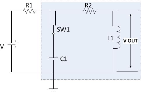
I am trying to determine the transfer function for the following circuit (within the dashed box):

RLC Circuit

I have searched around on the internet and have only managed to find a hand full of examples where the R and L are in parallel with a resistance in series with L, none of which have helped so far. I have been trying to derive the transfer function for the circuit for some time with no success.

I would really appreciate if someone could walk me through how to derive the TF or point me in the right direction.

Thanks in advance Ben

\$\endgroup\$
6
  • \$\begingroup\$ Does the switch do anything? \$\endgroup\$
    – Andy aka
    Commented Mar 21, 2015 at 19:16
  • \$\begingroup\$ The switch is only used to choose between charging and discharging the cap, when connected to R1 it will charge and then when connected to R2 i will discharge. I think this is what is causing me the issue as all the examples i have found have a source powering the RLC circuit, where as in this one the capacitor is the source. \$\endgroup\$ Commented Mar 21, 2015 at 19:18
  • 1
    \$\begingroup\$ Strictly speaking a transfer function doesn't exist for a non-linear circuit as yours (because of the switch). You might however find an "averaged" transfer function, as it is commonly done when analyzing switching power supplies. \$\endgroup\$
    – Roger C.
    Commented Mar 21, 2015 at 19:27
  • \$\begingroup\$ You must define how the switch operates in terms of frequency of operation and duty cycle or the circuit is not analyzable. \$\endgroup\$
    – Andy aka
    Commented Mar 21, 2015 at 19:30
  • \$\begingroup\$ Sorry i haven't been very clear about the functionality of the switch, initially the switch will make a connection between the capacitor and R1 allowing it to charge, once the capacitor is fully charged (after several hundred microseconds) the switch is set to the other position. it remains in this position until the RLC circuit has completely discharged down to 0V. I'm not sure if i could have represented it as just the RLC part with an impulse being applied across C1. From simulation the RLC part appears to behave like a second order system. \$\endgroup\$ Commented Mar 21, 2015 at 20:01

1 Answer 1

1
\$\begingroup\$

Your circuit doesn't have a transfer function. What you can do is compute the output voltage \$v_{o}(t)\$ after the position of the switch is changed from \$R_1\$ to \$R_2\$. For convenience I use the symbols \$R=R_2\$, \$C=C_1\$, and \$L=L_1\$. I assume that the capacitor has been connected to the voltage source via \$R_1\$ for a sufficiently long time such that the voltage at the capacitor equals \$V\$. If the position of the switch is changed at time \$t=0\$, you get the following equation in the Laplace domain:

$$\frac{V}{s}=I(R+sL+1/sC)\tag{1}$$

where \$V\$ is the voltage at the capacitor at \$t=0\$, and \$I\$ is the current in the RLC circuit, such that the output voltage is given by

$$V_o=I\cdot sL\tag{2}$$

From (1) you get for the current

$$I=\frac{V}{L}\frac{1}{s^2+\frac{R}{L}s+\frac{1}{LC}}\tag{3}$$

which, combined with (2), gives for the output voltage \$V_0\$

$$V_0=V\cdot\frac{s}{s^2+\frac{R}{L}s+\frac{1}{LC}}=V\cdot\frac{s}{(s+\frac{R}{2L})^2+\frac{1}{LC}-\frac{R^2}{4L^2}}\tag{4}$$

The time domain function \$v_0(t)\$ is obtained by transforming (4) back to the time domain. Here you have to distinguish the following 3 cases, where I've used the symbols \$\alpha=R/2L\$ and \$\omega^2=\left|\frac{1}{LC}-\frac{R^2}{4L^2}\right|\$:

  1. \$\frac{1}{LC}=\frac{R^2}{4L^2}\$: $$V_0=V\frac{s}{(s+\alpha)^2}=V\left[\frac{1}{s+\alpha}-\frac{\alpha}{(s+\alpha)^2}\right]\Longleftrightarrow v_0(t)=V\left(1-\alpha t\right)e^{-\alpha t}u(t)$$

  2. \$\frac{1}{LC}>\frac{R^2}{4L^2}\$: $$V_0=V\frac{s}{(s+\alpha)^2+\omega^2}=V\left[\frac{s+\alpha}{(s+\alpha)^2+\omega^2}-\frac{\alpha}{(s+\alpha)^2+\omega^2}\right]\Longleftrightarrow \\v_0(t)=V\left[\cos(\omega t)-\frac{\alpha}{\omega}\sin(\omega t)\right]e^{-\alpha t}u(t)$$

  3. \$\frac{1}{LC}<\frac{R^2}{4L^2}\$: $$V_0=V\frac{s}{(s+\alpha)^2-\omega^2}=V\left[\frac{s+\alpha}{(s+\alpha)^2-\omega^2}-\frac{\alpha}{(s+\alpha)^2-\omega^2}\right]\Longleftrightarrow \\v_0(t)=V\left[\cosh(\omega t)-\frac{\alpha}{\omega}\sinh(\omega t)\right]e^{-\alpha t}u(t)$$
\$\endgroup\$
1
  • \$\begingroup\$ Matt, Thank you for the answer :) this is exactly what i needed. To everyone else thanks also for your help. \$\endgroup\$ Commented Mar 22, 2015 at 22:07

Your Answer

By clicking “Post Your Answer”, you agree to our terms of service and acknowledge you have read our privacy policy.

Not the answer you're looking for? Browse other questions tagged or ask your own question.