Hi I am not sure if I understand this! Ok if I have a power source of 5 volts which then has a resistor of 6ohms and another resistor of 4ohms in parallel with a volt meter would I add the two resistors together and and times the second resistor by the volts to get the volts shown on the Vout Can you explain why I need to times the second restistor by the volts.
-
4\$\begingroup\$ Welcome to EE.SE, Nick. We love schematics more than words (and yours are a little garbled). There's a nifty drawing tool built into the editor. Edit your post and add a little schematic. There's a voltmeter down at the bottom. Double-click a component to edit its annotation or value. \$\endgroup\$– TransistorCommented Apr 22, 2016 at 23:13
-
\$\begingroup\$ Two sentences in a paragraph.... The second sentence contains 65 words.... confusing rather than enlighting.... Tiring..!! \$\endgroup\$– soosai stevenCommented Apr 23, 2016 at 1:06
-
2\$\begingroup\$ Please edit your question to make it clear what the circuit is. There are currently two answers. Either could be correct depending on how you interpret your circuit. I think you are describing a voltage divider but I'm not sure about this. A picture will clarify this and as @transistor pointed out there is a great tool on this site for drawing schematics. \$\endgroup\$– Warren HillCommented Apr 23, 2016 at 9:47
2 Answers
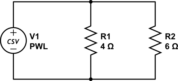
If I deciphered correctly: (please use diagrams in the future, you'll get a much friendlier reception)

simulate this circuit – Schematic created using CircuitLab
As always you can draw a good analogy between water pipes. Imagine the easy edge case where both resistors have the same value; the resistance should be 1/2. If there are 3 it should be 1/3 etc. With that in mind read the wiki article: https://en.wikipedia.org/wiki/Series_and_parallel_circuits
For your particular case: $$\frac{1}{R}= \frac{1}{4Ω} + \frac{1}{6Ω}$$
Edit: Read about Oms law: $$ I = \frac{V}{R}$$ You first determine how much current flows through both resistors, then calculate the rest. Why this is so should really be quite obvious if you look at the problem from the right angle. The right is for most people the analogy to water pipes.
-
\$\begingroup\$ Nice explanation and schematic, but I think he actually has a voltage divider question with 6 Ohms in series with the source and he's measuring voltage across the 4 Ohm resistor :) \$\endgroup\$ Commented Apr 22, 2016 at 23:56
-
\$\begingroup\$ I see it now, damn. OPs question is very spaghetti though. \$\endgroup\$– caconyrnCommented Apr 23, 2016 at 0:01
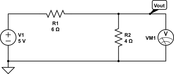
I believe the question is about the circuit below.

simulate this circuit – Schematic created using CircuitLab
This is a simple voltage divider that divides the input voltage with a certain number that is set with the two resistors R1 and R2. The number that the input voltage will be divided with can be calculated with this formula:
R2/(R1 + R2)
in your particular case it would be:
4/(6+4) = 4/10 = 0.4 .
In order to calculate the output voltage simply multiply the input voltage with number calculated before. This would give
5V * 0.4 = 2V
There is plenty of information available on the internet about voltage dividers if you want to read up for more.
