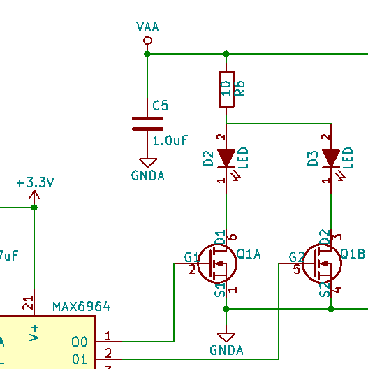
I have designed a simple circuit to drive LEDs using a MAX6964 I2C LED driver/GPO chip. Unfortunately, I somehow missed missed that the outputs are open-drain current-sinking outputs. This is not working because my circuit uses an N-channel mosfet in a low side configuration. From my research on this site, I found a few articles on N-channel and P-channel mosfets but none seem to address my specific question.
From my readings on this site, the N-channel gate needs a positive voltage to switch it. Again, unfortunately the output of my Max6964 is a current sink not a current source. I have already made some pc boards with the design that includes surface mount parts. I am trying to "salvage" these pcbs with the smallest possible change of components and/or trace cutting & rewiring. Here are my thoughts:
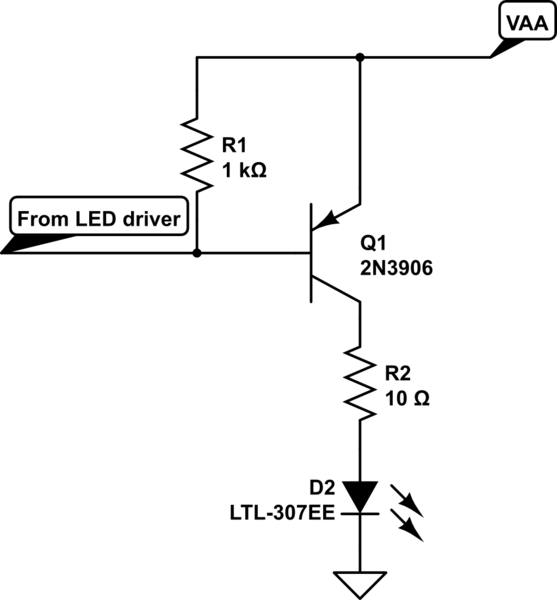
Simply replace the the N-channel mosfet with a P-channel mosfet. Is that correct? My hunch is this will not work.
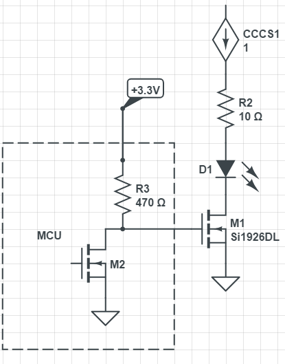
Leave in the N-channel mosfet and add a pull up resistor (value?) between the gate and the supply (VAA) work? This would invert the logic for turn on the LED but I can live with that.
Since the Max6964 can sink 50mA on each port, remove the N-channel mosfet, jumper the gates to the sources, and increase the value of resistor R6 to some higher value (~100 ohms) to limit the current. I am trying to maximize the intensity of the LEDs so I am not sure this option is the best.
Here is the simplified Max6964 output port from the data sheet:
[![Max6964 simplified output port][2]][2]
Thanks a bunch in advance for any feedback!
[IMPORTANT EDIT] VAA is +5V PWM signal. So although I liked the pull up idea, I don't think it will work.
[EDIT 2016-04-20 proposed:]


