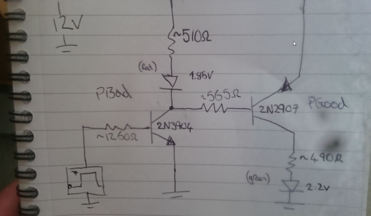
im trying to use a 0-7V control signal to switch an NPN controlling a LED but then using collector of the NPN to switch a PNP. So when control V is low NPN LED is on and PNP LED is off and when control V is High NPN LED is off and PNP LED is on. Is the below circuit a good way of doing this? i have imagined this circuit in my head and cant find anything similar, maybe for good reason?
\$\begingroup\$
\$\endgroup\$
1
-
1\$\begingroup\$ That circuit will turn both on and off at the same time. You need one NPN for the red LED and you need your whole circuit - NPN and PNP - without the red LED to switch the green. \$\endgroup\$– TransistorCommented Oct 6, 2016 at 11:11
Add a comment
|
1 Answer
\$\begingroup\$
\$\endgroup\$
8
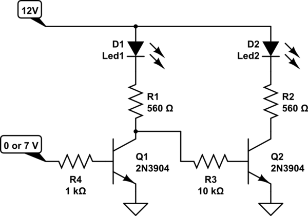
Your circuit will turn both LEDs on or both LEDs off.
This will solve that:

simulate this circuit – Schematic created using CircuitLab
-
\$\begingroup\$ this looks great too. will test both out. many thanks! \$\endgroup\$– NanchildCommented Oct 6, 2016 at 11:45
-
\$\begingroup\$ I can guarantee you that this one will suit you better than Rohat's one as his one is just a voltage buffer. This one has gain making it switch in a nicer way. \$\endgroup\$ Commented Oct 6, 2016 at 11:47
-
\$\begingroup\$ This one is better than mine, of course. As I said before, I thought that the input has the same level as Vcc. \$\endgroup\$ Commented Oct 6, 2016 at 11:52
-
\$\begingroup\$ that really is a lovely circuit! many thanks to you both, i can now see why mine didnt work in the first place! \$\endgroup\$– NanchildCommented Oct 6, 2016 at 11:53
-
1\$\begingroup\$ @anhnha You mean both LEDs will be on, true but since R3 is 10 k ohm the current through D1 will be significantly less than the current through D2 making D1 significantly less bright than D2. If that bothers you you could add a resistor in parallel with D1 to make the voltage across D1 low enough for it not to light up. \$\endgroup\$ Commented Oct 14, 2016 at 21:04

