I am rather new to electronics, and I am reading up on the topic. I came across the term ground. I get the large scale applications like the wires leading into the ground from power lines, but how is ground applied to smaller, simpler circuits? Imagine a circuit with a battery and an LED. Wires lead out of the positive and negative side of the battery and connect to the points on the LED. Where would the ground be on that circuit?
-
\$\begingroup\$ In line with Ignacio's answer, here's a good example. Notice the ground is chosen to be between both batteries. markhennessy.co.uk/articles/power_supply.gif Now it would be bad if the negative terminal of the lower battery came into contact with ground of another circuit, or the actual ground! That would make the negative supply tied to 9v, and the positive supply tied to 18v. \$\endgroup\$– krb686Commented Mar 25, 2014 at 21:41
-
2\$\begingroup\$ It's a bit like asking where the "ground floor" is. In a building, it's usually street level. In an airplane, the floor is 30,000ft above "earth", or maybe 20ft above the tarmac, it doesn't matter when you're measuring relative to the plane, but it gets trickier if you try to jump from "ground floor" to "earth". \$\endgroup\$– John UCommented Mar 26, 2014 at 11:28
5 Answers
Traditionally, "ground" is the lowest potential in a circuit, e.g. the minus side of a battery or DC supply. In an AC circuit, such as the 110 volts AC coming into your house (at least in the US), ground will be the wire closest to the earth potential (i.e. you can usually touch the white wire, which is the ground or neutral wire, but get a bad shock if you touch the black "hot" wire -- but don't count on these conventions, as the wiring may be incorrect and/or there may be a ground fault in your wiring).
Below, in the simple DC circuit on the left, there is an explicit wire connecting the ground lead from the battery to the minus side of the LED. In the circuit on the right, ground symbols (the open triangles) are used instead; in a large circuit there will be ground symbols scattered all over a schematic, all assumed to be connected together. (Sometimes other but similar symbols are used for ground.) These two circuits are identical.
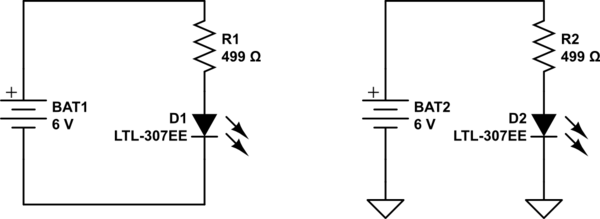
simulate this circuit – Schematic created using CircuitLab
The one exception to the ground being the lowest potential in a circuit is when you have both positive and negative supplies, such as in the following circuit:
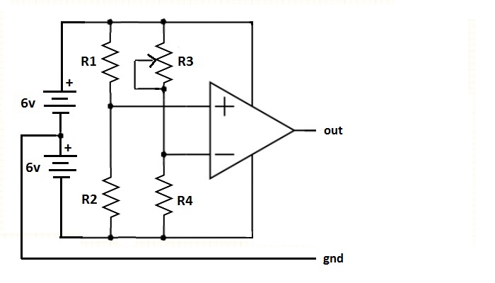
Here there are two batteries, so you have both a +6v supply and a -6v supply, relative to the ground lead between them. The reason for the two supplies is the comparator, which needs both positive and negative supply voltages. This means the output of the comparator will also swing both positive and negative. Op-amps are another type of IC that sometimes require both positive and negative supplies. However it is more common for both op-amps and comparators these days to require only a positive supply.
Sometimes there may be more than one ground is a circuit; this is typical in circuits that have both digital and analog circuitry, and is done to minimize noise. There will be only one point on the circuit where the two grounds are connected. Another way that noise is mitigated on printed circuit boards (PCBs) is to have an entire layer of the board dedicated to being a ground plane. This makes it easier to connect all the pins and other components of the circuit that need a ground by just dropping a via down to the ground plane. If a ground plane is not used, traces have to be routed all over the board to connect all the grounds together.
-
3\$\begingroup\$ It's not really true that "Traditionally, "ground" is the lowest potential in a circuit". In fact when PNP transistors were preferred Ground was traditionally on the +Ve battery terminal and the Supply was -Ve. See muzique.com/lab/fuzzface.htm for context. \$\endgroup\$ Commented Mar 26, 2014 at 9:53
"Ground" is a much abused term in electricity and electronics. Occasionally, particularly in AC power distribution and some radio antenna systems, it does mean "a connection to the earth".
However, in most electronics, particularly portable battery-operated devices, "ground" is just the point in the circuit that the designer chose to call "zero volts" and to use as a reference when measuring voltages elsewhere in the circuit. I think it would be better to call it "reference" or "common", but we seem to be stuck with misusing "ground".
In most circuits these days, "ground/reference" is the most negative terminal of the power supply, so voltages elsewhere are positive relative to "ground".
In some cases, the positive terminal of the power supply is "ground", and voltages elsewhere are therefore negative (there's one logic family that is supposed to run from a -5.2 volt suppply).
In many analog circuits, particularly those using op-amps, "ground" is the middle of the power supply, so we have both negative and positive voltages in the circuit.
To put it simply, wherever you like. The only requirement for a ground is that everything must pick the same ground in order to avoid unwanted current flows between different systems. The negative supply is the most common choice, but no more or less valid than any other.
-
\$\begingroup\$ Ok thank you for your answer, but why do you mean everything has to share the same ground? How do you make a point in the circuit the ground? And how would you, let's say, make a voltage divider using the ground if it can go anywhere? \$\endgroup\$ Commented Mar 25, 2014 at 21:57
-
\$\begingroup\$ You pick a point in the circuit, you say "That's ground.", and that point becomes ground. It becomes the 0V point when measuring voltages throughout the circuit. \$\endgroup\$ Commented Mar 25, 2014 at 22:08
-
\$\begingroup\$ I thought the ground had to lead to nowhere. If you just pick an arbitrary point on the circuit, then wouldn't it have voltage? And how would I build a voltage divider around that ground point? In all schematics I have found, the ground is just like a hanging wire. \$\endgroup\$ Commented Mar 25, 2014 at 23:27
-
\$\begingroup\$ Put another way, "ground" is simply a label you give to a particular voltage to help you and others think about what is going on. You don't do anything different with it. It's akin to saying that something -- like a tree -- is 5 meters away. That tree is all sorts of distances away from different locations, but from where you are standing (your ground) it is 5 meters away. \$\endgroup\$– sbellCommented Mar 25, 2014 at 23:30
-
\$\begingroup\$ You don't build a voltage divider "around [a] ground point", you build it between two voltages. And then it weighted averages them. \$\endgroup\$ Commented Mar 25, 2014 at 23:50
You seem to be confusing (as I did) ground with protective earth. "Ground" is the reference point for the voltage potentials in the circuit, is designated 0V, and all other voltages are compared to that. Consider this circuit, where power is provided from two 9V DC batteries in series:
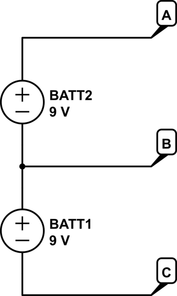
simulate this circuit – Schematic created using CircuitLab
Any of the points A, B, and C may be considered ground but the circuit will be considered to have different voltages depending on which point is selected. If point A is ground, B is -9V, and C is -18V; if B is ground, A is 9V, and B is -9V; if C is ground, A is 18V, and B is 9V.
Protective earth, on the other hand, is used in high-voltage AC circuits to provide a safe path for unexpected current, protecting people and property from electrocution, failure, and fire.
Unfortunately, both "ground" and "protective earth" are often referred to simply as "ground" (especially, in my experience, by people who work exclusively with one or the other but not both).
Caveat: I'm new at this too, and hoping to learn from this answer as well. If there's anything I've missed (or I'm just plain wrong), please don't hesitate to comment and/or edit! Thanks.
-
\$\begingroup\$ So is it customary to select the point of lowest voltage as the ground? If so, would you just find that using a voltmeter? \$\endgroup\$ Commented Mar 26, 2014 at 12:23
-
\$\begingroup\$ A voltmeter measures the difference in voltage between two points. Connecting the probes to A and B will always say 9V (or -9V, depending on where the positive probe is) regardless of what the circuit is. If there's a single DC supply, generally it's negative terminal will be designated ground unless there's a good reason to do otherwise (such as the guitar effect circuit in @akellyirl's answer). \$\endgroup\$– CalrionCommented Mar 27, 2014 at 0:12
As others have said, the Ground reference in a circuit is a Relative point; i.e. Voltages are defined in that circuit with respect to the chosen Ground reference.
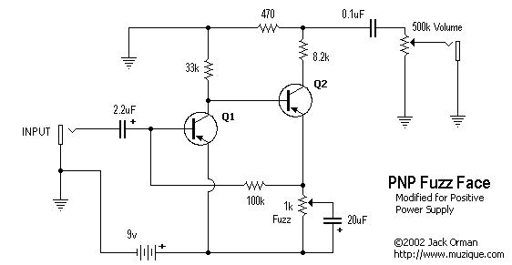
Historically Germanium Transistors were mostly available as PNP devices. In these circuits a Negative supply was the norm with Ground being chosen as the +Ve potential.
The circuit below is from a classic Guitar effect unit (source)
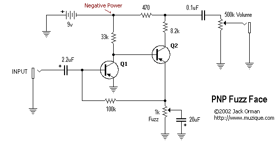
Notice the +Ve of the battery is labelled as Ground and the power is Negative.
But this ground scheme may be incompatible with other Guitar Effect units....
So it can be redrawn:
