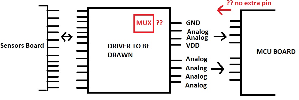
I've been searching for a way to add an extra pin to a driver board. The MCU board that i'm using only has 8 pins on the left side and i'm already using all of them. 2 are for powering the driver and the other 6 are analog inputs. I need only one more control which has to be a digital output. Is there a way to put some kind of multiplexer on the driver and use the MCU pins that i'm using as analog but as digital outputs to control the mux outputs? I know it is kinda strange what i'm asking, but i have to have a solution for the lack of MCU pins.

-
\$\begingroup\$ Have you tried using a pin from the right side? \$\endgroup\$– Ignacio Vazquez-AbramsCommented May 28, 2014 at 21:50
-
\$\begingroup\$ Hi. I can't. the driver board has to enter on this side of the MCU board. \$\endgroup\$– Electronics_GuyCommented May 28, 2014 at 22:08
-
\$\begingroup\$ What MCU are you using? How often are you reading the analog signals, and how often do you need to change the digital output? You don't show any digital lines going into the driver board. Just one lead? Why is the VDD and GND for the driver board coming from the MCU pins (as currently drawn) instead of being connected directly to VDD and GND? \$\endgroup\$– tcrosleyCommented May 28, 2014 at 22:41
-
\$\begingroup\$ i'm using the ATmega328 MCU chip. i'm constantly reading the analog channels (still don't have a timer because i'm just testing inside the main loop). There is no digital lines going into the driver =/. that is what i need. The VDD and GND are coming from the MCU board because the power is comming from a battery connected to the MCU board. \$\endgroup\$– Electronics_GuyCommented May 28, 2014 at 22:48
-
\$\begingroup\$ @user43113 Sorry, my bad. I didn't look at your drawing close enough. I thought you had only 8 pins available on your MCU, rather than 8 pins coming from the MCU board. \$\endgroup\$– tcrosleyCommented May 28, 2014 at 22:51
2 Answers
Rather than try to use the same pins as both analog inputs part of the time and digital output(s), I would do the following:
Add an 8-channel analog mux to the driver board, such as the HEF4051B. The output of the mux will then go into one of the analog input lines currently going to the MCU board. Tie the enable lead \$\mathsf{\small \overline{\text{E}}} \$ to ground (always enabled).
Reconfigure the remaining seven analog inputs as digital.
Use three of the seven digital lines to select the 1 of 8 channels for the mux.
You now have four digital lines available between the MCU board and driver board.
-
\$\begingroup\$ Oh that seems like a good idea! I've never used analog mux's. Thanks for the advice \$\endgroup\$ Commented May 28, 2014 at 23:05
-
\$\begingroup\$ It's no different from what happens inside the ATmega328 -- when you select an analog channel for the ADC, this is driving an internal mux to select one of the analog inputs. I'm just moving that outside the chip (so you will leave the same channel selected all the time in the ATmega328, and instead manipulate the three external channel select lines). \$\endgroup\$– tcrosleyCommented May 28, 2014 at 23:15
-
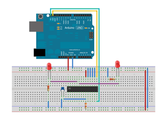
You could use an I/O expander like the MCP23016. It uses I2C to communicate with your Arduino/ATmega328. So basically you'll need only 2 pins from the arduino/ATmega328 to connect this chip and you'll get 16 I/O pins for exchange meaning you'll get 14 extra I/O pins. You can download a library for arduino here.
And also an example how to wire it for blink.

For the Arduino Uno the SCL and SDA pins are A4 and A5
-
\$\begingroup\$ You can use max 8 of these I/O extenders and create 128 new I/O ports (ADC4 and ADC5 of the ATmega328) \$\endgroup\$– HandokoCommented May 29, 2014 at 12:45
