6
\$\begingroup\$

I have some old ~100Ah car batteries. There is no mechanical damage, they were not overcharged or incorrectly used. I assume they are sulfated.

This is a theory from Wikipedia:

Pulses must last longer than the resonant frequency of the battery. Short pulses simply feed energy wastefully into the resistive components of this resonant circuit and virtually none into the battery. Electronic circuits are used to regulate the pulses of different widths and frequency of high current pulses. These can also be used to automate the process since it takes a long period of time to desulfate a battery fully.

But how to do it in practise?

  1. What voltage and current I need?
  2. When I should stop pulse charging?
  3. How to determine or estimate resonant frequency of the battery?

Answering please take note that I have some electronics and microcontroller knowledge, I have oscilloscope in my workshop.

\$\endgroup\$
7
  • 1
    \$\begingroup\$ See Battery-U: Sulfation. You cannot reverse sulfation from long-storage at low charge. \$\endgroup\$ Commented Jun 1, 2014 at 16:33
  • \$\begingroup\$ What is a battery's resonant circuit? \$\endgroup\$ Commented Jun 1, 2014 at 16:47
  • 1
    \$\begingroup\$ @LeonHeller After some more research I think thats about mechanical resonance frequency. Look what I found: en.wikipedia.org/wiki/Battery_regenerator#Regeneration \$\endgroup\$
    – Kamil
    Commented Jun 15, 2014 at 10:10
  • 2
    \$\begingroup\$ The second commentor seems to know what he's talking about and appears to have some experience with it: godlikeproductions.com/forum1/message1755445/pg1 \$\endgroup\$
    – horta
    Commented Jun 16, 2014 at 14:58
  • 1
    \$\begingroup\$ If you have a scope, watch the rise and fall times of the high-voltage spikes. If you see no sloping the frequency is too fast. You should see it spike and inverse-curve back down before it spikes up again. \$\endgroup\$
    – EkriirkE
    Commented Jun 17, 2014 at 7:00

1 Answer 1

2
+50
\$\begingroup\$

Usually desulfation is achieved by passing "high voltage" (often around 50V) through the battery. The simplest way to do this would probably be by using a 555 timer and a few other components to send the high voltage pulses into the battery. Generally desulfator circuits draw around 300mA, though it can fluctuate widely depending on the design you use. If it starts drawing >600mA then chances are you're doing it wrong.

Desulfation will usually take quite a while before the effects are completely reversed--some people have stated it can take up to a month, and possibly even more. You'll need to do some extensive testing on your circuit to make sure it's not drawing too much current and that it stays cool, so that it will be able to last that long. Ideally you would have it powered from a wall wart, so you don't have to worry about draining any other batteries. Frequency will need to be around 1KHz, if I am not mistaken.

So in short, the answers to your questions are as follows:

  1. You will need to be able to pulse around 50V to the battery, and have a power source capable of handling preferably >1A (even though the circuit should draw less than half that, it'd be a good idea to be able to supply more just in case).
  2. The charging will probably take a while. Once your battery can hold a charge of around 13.5V then it should be ok.
  3. Just assume around 1000 Hz, though you'll want to make it adjustable.

NOTE: I just found a quick n' dirty battery desulfator circuit on Instructables. I don't normally recommend following electronics circuits from there, but this one may be worth a try. Here is the link: Battery Desulfator. The above project uses the following schematic: Battery Desulfator Circuit
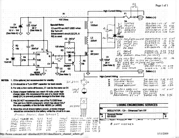
I hope this helps, and I wish you the very best of luck! Please post back here with the results once you have them!

\$\endgroup\$
2
  • \$\begingroup\$ This appears to be the circuit from this forum here: leadacidbatterydesulfation.yuku.com/topic/1193/… \$\endgroup\$
    – EkriirkE
    Commented Jun 17, 2014 at 6:54
  • \$\begingroup\$ Thanks for the link, EkriirkE. It does look similar, though I think the circuit above has a few corrections. I'd have to take more time to look at it to make sure, though \$\endgroup\$
    – DerStrom8
    Commented Jun 17, 2014 at 11:58

Your Answer

By clicking “Post Your Answer”, you agree to our terms of service and acknowledge you have read our privacy policy.

Not the answer you're looking for? Browse other questions tagged or ask your own question.