0
\$\begingroup\$

I'm currently building a DC-DC step up circuit to step up 3V to 100V. I don't want to use transformer because i want to keep the circuit as small as possible. My thought is ... building a 30V-output circuit using MIC2250, then build a boost circuit to boost the voltage 3-4 times. The 30V output has been achieved, but the boost doesn't work. The diagram is as below. The boost suggest from some websites
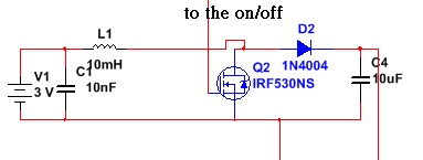
I was thinking of repeating this circuit 2 to 3 times in order to step up the overall voltage 2-3 times. but it doesn't work.

My another design is to use IC solely. some ICs like LT3757 and LT3783 seem to fit my design, but I just don't find any suggested circuit to boost from 3V to 100V. I tried MCP1652 before by following the circuit in the datasheet. Although the datasheet clams that the circuit can step up the input to 100V, I just can't do it. The maximum I got was only 40V.(I emailed the technician from MCP...he asked me to find the solution on the internet myself...poor aftersale service...) the only suggested circuit from 5V to 350V in LT3757 requires transformer, but i just try to avoid transformer.

Can any body share you idea with me about the circuit stepping up from 3V to 100V? Iout = 0.1A will be good enough. slightly smaller will be acceptable too.

\$\endgroup\$
6
  • 2
    \$\begingroup\$ The diagram shows it with 3volts on the input not 30volts - are you sure this is correct. Also what output current do you need and what is the 3V power source? 10mH inductors that are effective for this type of application are probably going to be no-smaller than a flyback transformer. \$\endgroup\$
    – Andy aka
    Commented Jun 14, 2014 at 8:33
  • 3
    \$\begingroup\$ Assuming 50% efficiency 100mA out at 100V means ~ 6A input on average. Depending on the duty cycle that might mean ~ 10A peak. Is your circuit, especially the 3V source, up to that? \$\endgroup\$ Commented Jun 14, 2014 at 9:42
  • \$\begingroup\$ I've built a similar circuit using parts I had around. It took 9V to 120V (low current draw). I don't know if you can get to 110V using this setup but you really need to change that diode to a Schottky. \$\endgroup\$
    – user34920
    Commented Jun 14, 2014 at 19:02
  • \$\begingroup\$ 3V here is not the exact input I did. I just want to check if the boost circuit is able to boost up 3/4 times. I've tried 6V or even 9V for both simulation and real application. It seems that this boost circuit is not ale to boost more than 2 times. \$\endgroup\$
    – user45538
    Commented Jun 15, 2014 at 4:30
  • 1
    \$\begingroup\$ Boosting 3V to 100V without transformer is hard, especially if you don't have oscilloscope (or you have one?). I think that blaming Microchip for poor aftersale support is inappropriate. Their support is great, they have nice educational documents, starter kits etc. You could ask about this on Microchip forum or here instead of asking MCP technical support. There is nothing wrong with such MCP technican response. \$\endgroup\$
    – Kamil
    Commented Jun 15, 2014 at 14:49

4 Answers 4

3
\$\begingroup\$

1N4004 diodes are inappropriate for this application because they have a very long \$ t_{rr}\$ reverse recovery time. Use an ultra fast UF4004 here.

Assume output voltage is 100V and current is 100mA. Then ton/toff is about 2.5, and peak inductor current will be 700mA (the inductor must not saturate - so that's a big inductor). On time will be about 30usec and off time 12usec, so about 24kHz.

It's feasible if the parts are properly rated- but the most likely culprit if it does not work when fed with a high capacity 30V bench supply is the inductor- use one that will not saturate with 1A or more.

\$\endgroup\$
0
3
\$\begingroup\$

Avoiding a transformer to keep the circuit small ... doesn't work so well.

See Spehro's answer : to avoid saturating the inductor in a flyback convertor, you need to keep the current low, or use a big inductor. The problem is that you are storing energy in the inductor core at low voltage, and releasing that energy (in a fast pulse) at high voltage. And it will only hold so much energy before it saturates.

With a transformer, while the primary winding is storing energy, the secondary is already pulling energy out (at higher voltage but lower current) so very little energy is actually stored in the core. This means you can transfer much more energy for the same size of core. Or use a smaller core for the same power delivery.

Something like this might be close to what you want, about 1.6*1.6*1.6cm to deliver about 6W (0.06A at 100V). You could drive its 3.3V secondary from an H-bridge at 100kHz and extract power from its primary, with a bridge rectifier made from those fast diodes. Or wind a custom transformer on a core like this or this smaller one to get exactly what you need. I haven't done the math to design a 10W supply around either of these cores. It may be better to look at application notes for some of the ICs you mentioned for guidance on winding suitable transformers.

\$\endgroup\$
2
  • \$\begingroup\$ Thanks for your information. You would also suggest me using transformer, right? By the way, where can I find some tiny transformer? What I have now is very big, ~6cm*6cm*6cm. \$\endgroup\$
    – user45538
    Commented Jun 15, 2014 at 4:27
  • \$\begingroup\$ I think he means that coil for converter without transformer will be larger than transformer. However at 750kHz (MCP1652 works at that freq) - there is no need for big coil core for 10W converter, but 3V->100V design may require thick wire (low coil resistance). \$\endgroup\$
    – Kamil
    Commented Jun 15, 2014 at 14:53
0
\$\begingroup\$

Im guessing that your 3V power source was unable to deliver enough power/current and thats why you had 40V output instead of 100V on converter built on MCP1652.

You should measure input voltage when converter is running.

\$\endgroup\$
2
  • \$\begingroup\$ 3V here is not the exact input I did. I just want to check if the boost circuit is able to boost up 3/4 times. I've tried 6V for MCP1652. The maximum output is still ranged from 40V-44V \$\endgroup\$
    – user45538
    Commented Jun 15, 2014 at 4:25
  • \$\begingroup\$ OK. So there must be a problem with too high mosfet resistance, too slow mosfet or too high coil resistance. These factors determine coil current and how fast this current changes. Fast current change on coil produces high voltage on coil. Faster and higher current change produces higher voltage. Can you edit your question and add your coil photo? Or maybe whole MCP165x circuit photo. \$\endgroup\$
    – Kamil
    Commented Jun 15, 2014 at 14:38
0
\$\begingroup\$

It is conceivable to use tapped inductor (auto-transformer). The mosfet switches the tap' the right side goes to the diode. The idea is to avoid exhausting duty cycle control range limitations. As bonus MOSFET sees lower voltage.

\$\endgroup\$

Your Answer

By clicking “Post Your Answer”, you agree to our terms of service and acknowledge you have read our privacy policy.

Not the answer you're looking for? Browse other questions tagged or ask your own question.