3
\$\begingroup\$

DC Wattmeter

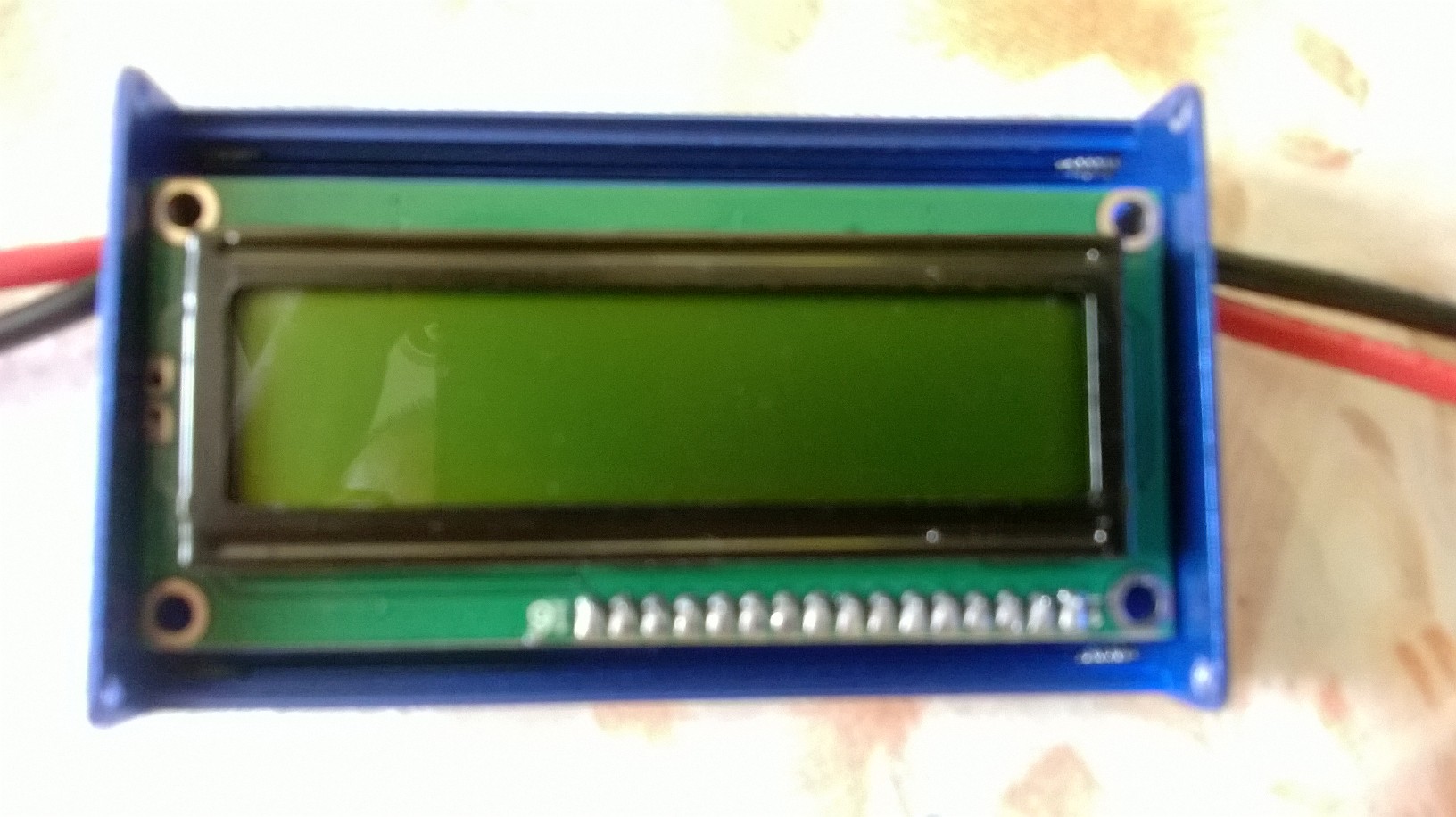
I have an inexpensive in-line DC Wattmeter that I often use to measure yield from Solar Panels / Modules and other energy sources with reasonable accuracy and resolution. It has a 16x2 LCD display (1602 STN) that displays 4 values simultaneously namely: Voltage (V), Current (A), Power (W) and Energy (AH). It uses a 8MIPS uC and has a Data Queue / Sequence time of 2 secs. It is rated for 0-60V and 0-100A DC. The wattmeter is a one stop solution as opposed to multiple DMMs or very expensive Data Loggers.

I am now trying to store the values displayed (Data Logging) for various downstream uses. The whole unit is sealed with only the 16 pins of the LCD remaining exposed (and thereby exploitable). All 16 pins are in use.

Is it possible to tap into those values being passed and either:

  • write them onto a SD card or
  • transmit to a PC/laptop over USB for display and storage.

The efficiency or accuracy of the unit should not be compromised in the due process.

\$\endgroup\$
3
  • 7
    \$\begingroup\$ A picture would help. It is possible, but difficulty and risk of breaking it during experiments depends on the type of connection. If this is a typical 16x2 dot matrix character LCD it should be fairly simple as the interface specifications for them are published. You'd need a moderately fast micro to watch and capture the data, and write it to an SPI interfaced SD card or push it up a serial or USB link to a PC. If it's a calculator-type segment LCD and the pins you see are the bare segments and selects, its a bit tricker but still do-able once you understand that sort of interface. \$\endgroup\$ Commented Jul 31, 2014 at 17:11
  • \$\begingroup\$ How come you don't want to use shunts and inamps to get the data how you want it? \$\endgroup\$ Commented Jul 31, 2014 at 17:29
  • \$\begingroup\$ Is there any reason you could just connect them to an Arduino or other MCU and use a data-logger? If not then @ChrisStratton should make his comment into an answer as it is correct \$\endgroup\$
    – Funkyguy
    Commented Jul 31, 2014 at 18:54

1 Answer 1

2
\$\begingroup\$

This would be simple, as you are essentially going to have to create the LCD driver's control interface in code. Assuming an 8 bit interface, you need between 10 or 11 pins (If R/W is used instead of tied as Write mode). If 4 bit, then you need 4 less. As the HD44780 LCD protocol is fairly well known, it would only be a matter of listening to the data pins when E is toggled, then parsing the data. Data is ASCII, while the commands are simple to understand. At that point you can log it to an SD card, or send it via serial or whatever.

The biggest issue will be timing. Not knowing how often the mcu writes to the lcd, or how fast, timing will be an issue. Not to mention, any Arduino library overhead. DigitalRead() will take much longer than direct reads, so it's suggested that you code it directly. A quick google shows no one else has produced a HD44780 sniffer or interceptor. This is essentially a logic analyzer. Keep in mind you could simply read and throw the data to a computer to process, as that may be faster.

Oh, and if you do this, be sure to share it online and blogs and stuff. A HD44780 sniffer like that is sure to be popular.

\$\endgroup\$

Your Answer

By clicking “Post Your Answer”, you agree to our terms of service and acknowledge you have read our privacy policy.

Not the answer you're looking for? Browse other questions tagged or ask your own question.