2
\$\begingroup\$

Im doing a project with a PIC18F452 and I will have to use USART. Thus, I bought a FTDI Basic breakout board (from Sparkfun) to make debugging easier. The board is the 5V version.

I already tested FT232R with a loopback circuit and Putty (on Windows) and it works well. I also tested PIC with a loopback circuit and it also works well. However I can't get FT232R to work with PIC. In the microcontroller I have USART configured with 9600kbaud, 8bit, no parity (same as PC side), RX with interrupt. Im just sending data from PC to PIC. When PIC receives something prints it on LCD. The problem is PIC isn't receiveing anything. So I picked up a osciloscope probe and the results are these:
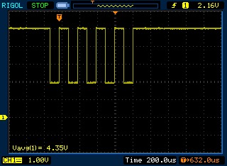
enter image description here

The signal doesn't touch the GND! Thats why PIC doesn't detect data arriving at RX pin, right?

However if I disconnect FT232 TX pin from PIC RX pin, I get:
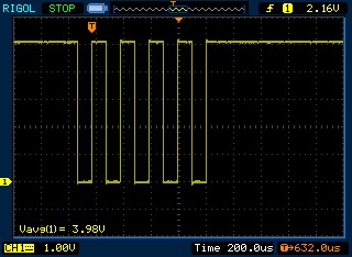
enter image description here

I have both GND (ft232 and PIC) connected.

Any suggestions on how to solve this?

Thanks!

\$\endgroup\$

3 Answers 3

1
\$\begingroup\$

Do you have the output driver enabled on the PIC UART RX pin? If it is driving a high level out, the voltage will go to 5V when the FTDI drives high, and something in the middle due to contention when the FTDI drives low.

(This may be a silly suggestion, depending on how the PIC UART configuration works, in which case I'm sorry.)

\$\endgroup\$
1
  • \$\begingroup\$ Double check the data sheet, but most of the time when you enable a PIC's UART it will automatically configure RX as input and TX as output regardless of TRIS bits \$\endgroup\$
    – ajs410
    Commented May 13, 2011 at 17:59
0
\$\begingroup\$

That often happens when you connect two transmitters together.

So, when you are looping back Knowing which one is the TX and which one is the RX is not a major concern. Either the FT232 or the pic is trying to be helpful and when the device uses TX it means the other devices TX. This is one of the many reasons naming conventions cause war.

Try swapping the TX and RX line and see if the line starts following the voltage you are expecting. If everything else is working it is going to be a hardware issue, and this would both cause the line not to go to 0V and no signal to be transmitted between the chips.

\$\endgroup\$
2
  • \$\begingroup\$ One way that I usually test this is to fire up your terminal of choice, let TX and RX float, scope both of them, and just hold down a key. Whichever line toggles is the line the PC sends the data out. \$\endgroup\$
    – ajs410
    Commented May 13, 2011 at 18:01
  • \$\begingroup\$ @ajs410, yes, I was just pointing out that the tests that had been completed would not have caught this error. \$\endgroup\$
    – Kortuk
    Commented May 13, 2011 at 19:52
0
\$\begingroup\$

While this doesn't directly apply to your problem with voltages, one common issue with not getting data into a PIC's UART is that you must remember to clear the OERR bit. If it ever gets set, the PIC will ignore all further incoming data until OERR is cleared.

\$\endgroup\$

Your Answer

By clicking “Post Your Answer”, you agree to our terms of service and acknowledge you have read our privacy policy.

Not the answer you're looking for? Browse other questions tagged or ask your own question.