6
\$\begingroup\$

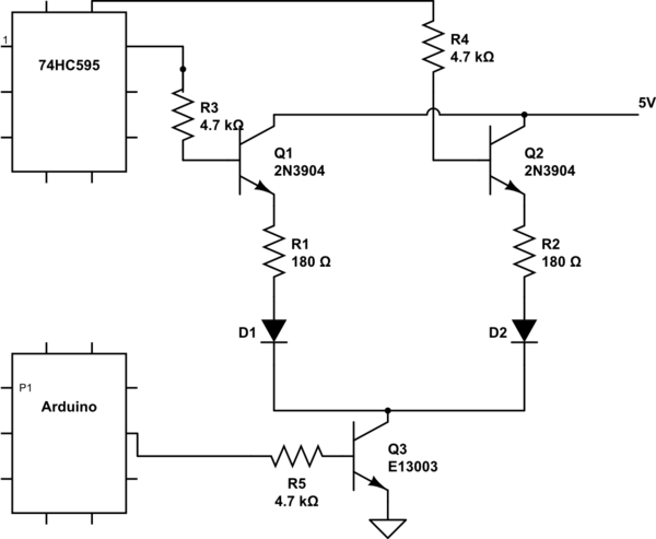
I have a 74HC595 shift register that I shift bits into from an 5v Arduino. The pins on the shift register is connected to the base of 2N3904 BJT's through a 4.7kOhm resistor. I have noticed that if I include the base resistor, my current to the base is 12.8uA and if I don't the base current is 13.1uA.

Since the figures are so small, do I even need a base resistor?

I should mention that I am trying to build a circuit for one of those fancy LED cubes. On the schematics are shown 2 diodes, but that will be expanded to 8 LEDs for each shift register.

schematic

simulate this circuit – Schematic created using CircuitLab

\$\endgroup\$
7
  • \$\begingroup\$ Could you perhaps provide a simple schematic? \$\endgroup\$
    – Dzarda
    Commented Oct 13, 2014 at 12:27
  • \$\begingroup\$ Yes of course. I thought it would be a bit excessive, but I'll make one \$\endgroup\$
    – Attaque
    Commented Oct 13, 2014 at 12:29
  • \$\begingroup\$ There is something wrong with your eeasurements. I would expect ~ 1mA with the ressistor, and ~ 30 mA without. A current in the uA range indicates that you either measured the wrong way, or the 595 output was low. \$\endgroup\$ Commented Oct 13, 2014 at 12:31
  • \$\begingroup\$ The op must clearly have an emitter resistor given what he says for the current. \$\endgroup\$
    – Andy aka
    Commented Oct 13, 2014 at 12:34
  • 1
    \$\begingroup\$ Q1 is an emitter follower, so R3 is not needed. If you want to scale the design to use a higher voltage source ie 12v instead of 5 for example you would want to use PNP transistors for the high side switching and than you would need a base resistor. \$\endgroup\$
    – Mike
    Commented Oct 13, 2014 at 12:44

2 Answers 2

13
\$\begingroup\$

The base resistors R3 and R4 are doing nothing useful. The circuit would be better with them replaced by wires.

You often see this kind of nonsense when someone designs a circuit by heresay and rules of thumb instead of actually undestanding the electronics. Whoever designed this heard somewhere that you're supposed to put a resistor in series with the base, but didn't bother to listen to the reason why and when this "rule" is appropriate.

Q1 and Q2 are used as emitter followers, so the base and emitter current will be nicely limited to safe values just because of the impedance of the load on the emitter. Adding base resistors will only make the output voltage less predictable.

Note that Q3 is used as a common emitter amplifier with the emitter tied to ground. In that case, something is needed to limit to the base current to a safe value. That is what R5 is doing.

So in summary, R3 and R4 are not needed and the circuit would be better off without them, but R5 is needed. Again, you have to undestand a circuit, not blindly apply rules of thumb, heresay, or any other type of silly superstition.

\$\endgroup\$
5
  • \$\begingroup\$ Thank you for your answer Olin. I'm the one who designed this, and you are absolutely right. I applied a rule of thumb when adding the base resistors. Luckily I have you good people to answer my silly questions. Another common thing I have seen, is to add a pull-down resister to the base, to help the transistor switch on/off faster. Would it make sense to put pull-down resistors at Q1 and Q2? \$\endgroup\$
    – Attaque
    Commented Oct 13, 2014 at 13:33
  • 2
    \$\begingroup\$ This circuit doesn't need pull-downs. The 74hc595 does that for you. \$\endgroup\$ Commented Oct 13, 2014 at 13:51
  • \$\begingroup\$ One thing that should be mentioned: generally high side switching (Q1 and Q2) is implemented using PNP transistors to avoid unnecessary voltage drop. In your circuit, the voltage at the emitter of Q1 and Q2 will sit at about 4.3 volts due to the necessary Vbe of 0.7 volts. If you use PNP transistors, then this voltage could rise all the way to the rail. And if you use PNP transistors, the base resistors would be required to limit the current. \$\endgroup\$ Commented Oct 13, 2014 at 19:26
  • 3
    \$\begingroup\$ The base resistors R3 and R4 would limit the current drawn from the 74HC595 if the supply of power to the emitters Q1 and Q2 were to fail. They could also protect the 74HC595 in the event that the transistors themselves were to fail. \$\endgroup\$
    – supercat
    Commented Oct 13, 2014 at 21:38
  • \$\begingroup\$ I found that when using the 74HC595 SR with FETs, a pulldown is needed (e.g. with an LED, you get a brief flash just before the SR initialises), but with BJTs, I have found that pull downs are not necessary. \$\endgroup\$ Commented Apr 2, 2022 at 7:57
1
\$\begingroup\$

There is one reason why R3 and R4 might be useful in your situation. As pointed out in the comments on the top answer:

The base resistors R3 and R4 would limit the current drawn from the 74HC595 if the supply of power to the emitters Q1 and Q2 were to fail. They could also protect the 74HC595 in the event that the transistors themselves were to fail.

While you're learning, if you make a simple mistake in your circuit (e.g. it's quite easy to disconnect Q1 and Q2 your 5V power supply) then the current will flow through base from the shift register and potentially exceed the 35mA absolute maximum rating for continuous output current on the 74HC595.

Or, maybe you're powering your Arduino via USB connected to your computer (it's possible you powered the 74HC595 from the Arduino, but you don't specify in your schematic). If the 5V supply on your circuit from your bench power supply, when you turn off your bench supply, now the LEDs will draw power from base and not the collector (tied to 5V in your circuit). The 74HC595 is ok for powering LEDs (below 35mA), as it happens, but if you had something a bit more powerful such as a fan drawing 200mA, then you're exceeding the max rating for the 74HC595. So, depends what you're doing and how careful you are.

Also, I've noticed that even when the 74HC595 is powered by a separate power source than the Ardunio, if VCC is disconnected, the 74HC595 can still draw power from the input pins connected to your Arduino (possibly either SER, RCLK, SRCLK... I haven't tested which). This is probably harmless for low power LEDs, but as well as exceeding the maximum current rating for your 74HC595, you could potentially exceed the Arduino's pin current limit if you have something on your BJT that draws a lot of current.

So, in your final design, R3 and R4 are maybe not useful, but while you're learning and tinkering (e.g. on a breadboard), a base resistor on a BJT could help you to prevent frying your 74HC595. But, as Olin points out, R5 is absolutely necessary to limit the base current to a safe value.

If you were using FETs, a pulldown resistor would probably be needed on the gate, but not a resistor from the 74HC595 and gate since the gate only ever draws a very small current. By the way, I've actually found FETs to be a bit friendlier when learning about transistors (2N7000 or similar is a great component to have handy). BJTs are very useful to learn though, and ideal for your schematic.
\$\endgroup\$

Your Answer

By clicking “Post Your Answer”, you agree to our terms of service and acknowledge you have read our privacy policy.

Not the answer you're looking for? Browse other questions tagged or ask your own question.