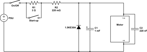
There are a number of components you might need - which ones you need, and their values all really depend on the type of motor and its condition etc, and the PSU and its condition etc.
The PSU although cheap is probably actually quite good, which is why it cuts off - it is protecting itself against damaging transients.
The problem is that when the motor is cut off, because it has coils, it tries to keep the current going by generating a voltage inverted to the original, which the PSU won't like.
Also, the problem could be that when motors start up, often they consume a lot more power than when they are running. So you may need a slow-start circuit. Again, this gets complicated but the series resistor might work. (R2). Or you could have a switch that you use to bypass a slightly higher value resistor once the motor has started turning. (R1).
Explanation of the component are below. There are further / alternative measures as well, but they get increasingly complex. From inductors to semiconductor motor driver circuits.
A small series resistor (R2). This resistor may need experimenting with. But I would not make it more than about 0.47 ohms. And at 0.47 ohms it should be rated at 8 watts or more, but you can combine resistors in series, or parallel, or a mix, and use lower power values. For lower than 0.47 ohms it can have a lower power rating. For example, for 0.22 ohms, the power rating just has to be higher than 3.52W. This resistor will help the PSU deal with whatever the motor throws at it, as well as make the other components below more effective. However its value should be kept as low as possible, as it will reduce the power available to the motor. Plus it will get hot.
A suppression diode. There are further / alternative measures as well, but they get increasingly complex. From inductors to semiconductor motor driver circuits.
Smoothing capacitor (C1) The capacitor may need fine tuning - too big and it itself may cause the PSU to cut out as it tries to charge. Too small and it will not counter the problems the motor causes. Make sure you get the polarity right or it will literally explode.
Transient suppressing capacitor (C2). This can be a small capacitor - the important thing is just to have it as close to the motor terminals as physically possible. However, there's a good chance the motor already has these internally, if for example it is a hand-held mini drill - perhaps open it up and see. If it is a bare motor however, you should add one to its terminals.
The 3 ohm start-up resistor (R1) should be 12 watts or more. You may want to experiment a bit with this, perhaps between around 2 and 4 ohms - too large and the motor may not start, too small and it may not inhibit the initial draw enough.
I would try the solutions in the following order:
- Suppression diode (because it's cheap, and always a good idea with DC motors)
- C2 - same as above but for AC motors too - but it probably won't solve your problem
- R1 - Most important for start-up draw
- R2 - Will make all other components more effective at shielding the PSU, but will cause slight power loss to the motor.
- C1 - May itself cause problems if too big, but if you're still having problems at this point, it's worth a shot.
Instead of trial and error, the better way to do it would be through measurements and various calculations, and/or using a made-for-purpose intelligent motor controller, but this obviously can get rather involved.

simulate this circuit – Schematic created using CircuitLab

