6
\$\begingroup\$

I'm trying to charge a LiPo with MCP73831 with 2 LEDs for status. I have an amber LED D1 which is on when VUSB is getting power from the USB connector, which means that it's charging. And a green LED D2 that should also light up when the battery is fully charged.

I'm having no luck getting the green LED D2 to light up when the charge is complete. I can see that the USB draw drops to near zero, and after being plugged into USB power for hours, the green LED will never light up. It's clearly done charging and the battery output voltage measures 4.2V, which is expected for a fully charged single cell LiPo battery.

Interestingly, when I poked around with the multimeter I got the green LED to illuminate. When I measured the voltage between GND and VBAT the green LED turned on while the probes were in contact with the circuit. When I removed the multimeter probes, the green LED immediately turned off.

So two questions:

  1. Why doesn't the STAT pin output HIGH when charging is complete as the datasheet claims it should? (which should light the green LED D2)
  2. Why does measuring the voltage between GND and VBAT cause the STAT pin to output HIGH?
  3. Does the multimeter measuring between GND and VBAT effectively place a high Ohm resistor between the two? And if so, would that fix this? Why?
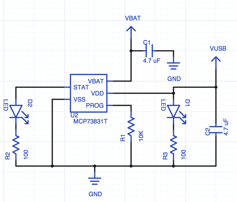
Charging schematic

Links to relevant things:

\$\endgroup\$
4
  • \$\begingroup\$ Could you provide the exact product number of the MCP78381 IC? There are numerous of voltage options on these for different kind of batteries. Maybe you have one for a higher voltage than your finished cell voltage? Just a guess. \$\endgroup\$
    – Dejvid_no1
    Commented Apr 12, 2015 at 21:12
  • \$\begingroup\$ These are the specific ICs. And this is the battery. \$\endgroup\$
    – Alex Wayne
    Commented Apr 12, 2015 at 21:16
  • \$\begingroup\$ Alex - see my added comments to Dejvid's answer (and +2 effective upvote :-). | Your IC is probably a 73831 as claimed - check that it is not a 73882 as they are functionally very similar but my comments re STAT pin would then apply. || Easy check. Remove battery and put as large an electrolytic capacitor as is available in its place. The charger should charge it to 4.3x volts and stop and the LED should work as you hope. You MAY need to trickle the cap up to about 3V with a high value resistor to V+ to get it going as it will probably initially otherwise see it as 'no battery present'... \$\endgroup\$
    – Russell McMahon
    Commented Apr 13, 2015 at 13:52
  • \$\begingroup\$ Once it is charged load it with a resistor, vcap will fall charging will restart , remove load and it will re-cycle. ||| I now think that Dejvid is probably correct BECAUSE the battery probably contains a protection IC to prevent overvoltage charging. If it did not, and some do not, it may well be dead by now. || Last important point.- Check the USB charging voltage input - it needs to be about 5.4V minimum at the input point. It should be above that, but do check. \$\endgroup\$
    – Russell McMahon
    Commented Apr 13, 2015 at 13:53

2 Answers 2

4
\$\begingroup\$

MCP73831T-3ACI/OT has a VREG of 4.35V. Your battery is finished charging at 4.2V.

The STAT pin will never go high since the regulator thinks that the charging is not finished.

\$\endgroup\$
9
  • \$\begingroup\$ Did I purchase the incorrect version of this IC? or did I fail to program it properly with the PROG resistor somehow? \$\endgroup\$
    – Alex Wayne
    Commented Apr 12, 2015 at 21:27
  • 1
    \$\begingroup\$ Yep. I think MCP73831T-2ACI/OT would work. It is also on Mouser. \$\endgroup\$
    – Dejvid_no1
    Commented Apr 12, 2015 at 21:29
  • \$\begingroup\$ Interesting... I guess that's it then. Was I damaging this battery charging it at 4.35V when it's 4.2V at maximum charge? \$\endgroup\$
    – Alex Wayne
    Commented Apr 12, 2015 at 21:33
  • \$\begingroup\$ @Dejvid_no1 Amended comment. This answer is essentially wrong - but you make an excellent and important point. The major issues is that he shows the STAT LED connected wrongly - if this is how he has really done it it will never light. You are correct that the charger voltage is higher than the battery data sheet says is correct - BUT it will almost certainly charge OK to that voltage - or burst into flames :-) :-(. \$\endgroup\$
    – Russell McMahon
    Commented Apr 13, 2015 at 1:59
  • \$\begingroup\$ Sorry, but the major problem is that he is trickle charging a Litium based cell to a over spec voltage. The STAT connection is fine. \$\endgroup\$
    – Dejvid_no1
    Commented Apr 13, 2015 at 7:32
0
\$\begingroup\$

The main problem MAY BE that your STAT LED is connected wrongly.
This depends on the IC actually supplied. The 73831 will work as you have shown. The almost functionally identical 73832 will not. Odds are your IC is as specified, but checking would be wise.


Dejvid is correct that a lower voltage option of the IC should be used - but the battery would almost certainly charge to the higher voltage if it was a bare battery. After reassessing Dejvid's comments I realised that the battery was probably being protected by an internal overcharge protection circuit. I have just rechecked the battery data sheet and see that they say "with PCM" - ie protection module. This is what has saved your battery. Some Asian sourced batteries which claim to have a PCM fitted do not have one. It seems that yours does ! :-).

The -3 version of the IC has min/typical/max Vterminate voltages of 4.317 / 4.35 / 4.383.
These voltages are too high for most LiPo batteries and will in many cases cause low cycle lifetimes and in some cases may cause spectacular flaming destruction. The PCM protects against this but should not be relied on.

Battery data sheet here
Note stated end point voltage of 4.2V. This is standard and should not be exceeded.

\$\endgroup\$
3
  • \$\begingroup\$ The truth table says STAT will go high = to VDD through the upper transistor of STAT push-pull stage. Shouldn't this light his LED? :) \$\endgroup\$
    – Dejvid_no1
    Commented Apr 13, 2015 at 5:33
  • 1
    \$\begingroup\$ That's one way to connect the led. It would be on while charging and off when done. That's not what I'm after though. The real problem here is that STAT should be 0V when charging and ~4.2V when charged. That should light the LED. So, while not exactly like the "typical" application it should work as wired, assuming I ordered the correct part that terminates charging at 4.2 V. \$\endgroup\$
    – Alex Wayne
    Commented Apr 13, 2015 at 5:48
  • \$\begingroup\$ I guess you're commenting on Russels interpretation. Your wiring is perfectly fine Alex. \$\endgroup\$
    – Dejvid_no1
    Commented Apr 13, 2015 at 7:30

Your Answer

By clicking “Post Your Answer”, you agree to our terms of service and acknowledge you have read our privacy policy.

Not the answer you're looking for? Browse other questions tagged or ask your own question.