1
\$\begingroup\$

I'm a total electronics n00b set out to create an intervalometer for my Canon EOS 350D camera which seemed super simple from the outset, but I got a bit blocked with creating a switch using a transistor.

I don't fully understand the inner workings of the transistor and got lost with things like having to saturate it, using a shorting resistor, calculating voltage / current / resistance, etc to get the whole thing to act as a binary switch.

The camera circuit I want to switch is super simple and low powered (each switch carries about 0.5 mA at 3.3 volts):
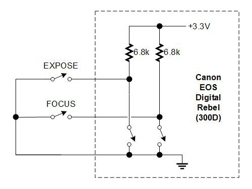
Canon remote circuit

(Source: http://www.covingtoninnovations.com/dslr/CanonRelease.html )

For now I only want to get the expose bit working as it seems I'll only need to duplicate that for focus.

For the controlling circuit I want to use an IOIO board, which is very similar to an Arduino being a programmable controller with a variety of I/O pins to interface with whatever you throw at it.

I have a bunch of P2N2222A transistors which even with my limited knowledge seem to be usable for this purpose and a resistor kit with 20 values, but I'm not really sure how to combine them or if I need to get a diode too to get this working.

So far I tried connecting the Canon circuit to the Collector and Emitter legs of the transistor and then connecting to the Base the 5V pin from a battery through a 2.2K resistor (which the transistor came with) hoping that it will just work, but nothing happened :) At the moment I'm trying to get it working without the IOIO just to simplify things and to not fry it if I do something wrong :)

I got the idea from this diagram by the way: enter image description here
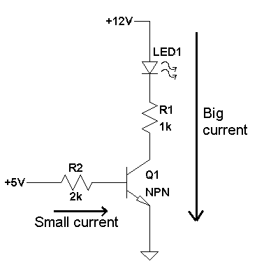
( Source: http://www.mayothi.com/transistors.html )

It seems strange to me though that the controlling circuit is not really a circuit just a one way thing, and reading about shorting resistors on other pages I guess I'd need to connect the grounds together somehow and use a higher resistance resistor in it? Or maybe even a diode? Please help!

\$\endgroup\$

2 Answers 2

2
\$\begingroup\$

While perusing the IOIO board link provided in the question, I noted that the board has some 5V tolerant open-drain digital output pins. Since the camera has built in pull-ups, as shown in the first diagram in the question, you should be able to connect the open drain pins directly to the camera. You will not even need the external transistors.

The current sink capability of the open-drain outputs is specifed at 20mA, which easily will handle the .5 mA mentioned in the question.

In this case, the camera "expose" and "focus" would be connected to open drain outputs, and the camera ground would be connected to the controller board ground.

edited to add:

I now note that the page you cited in the question, http://www.covingtoninnovations.com/dslr/CanonRelease.html, advises adding an optoisolator to the circuit if the camera will be powered by an AC adapter rather than the camera battery, as shown in the second diagram in the "Serial-Port Cable" section. That is probably a good idea. In that case, you could connect the optoisolator to an output pin on your controller board that is not an open drain pin, selecting a dropping resistor to set an appropriate drive current for the diode.

\$\endgroup\$
3
  • \$\begingroup\$ Oh great, that sounds like a really nice shortcut :) So I need to connect the expose / focus bits to an open-drain pin each and connect the camera ground to a IOIO ground pin? \$\endgroup\$
    – dain
    Commented Jul 13, 2011 at 15:09
  • \$\begingroup\$ @dain - The connections you mention are correct; I added that info to the answer, as well as some info on voltage isolation. \$\endgroup\$
    – B Pete
    Commented Jul 13, 2011 at 17:58
  • \$\begingroup\$ Thanks a lot Pete, really appreciate your help! I don't even own an AC adapter for the camera, so for now I should be fine without isolation. Will try to get it working as you described and report back :) \$\endgroup\$
    – dain
    Commented Jul 13, 2011 at 18:12
2
\$\begingroup\$

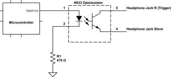
It is always a good habit to protect expensive electronics with an optoisolator. Here is a circuit you could use for the Expose Trigger, using the camera's stereo headphone connector. You can do the same connected to the headphone L for focus.

schematic

simulate this circuit – Schematic created using CircuitLab

\$\endgroup\$

Your Answer

By clicking “Post Your Answer”, you agree to our terms of service and acknowledge you have read our privacy policy.

Not the answer you're looking for? Browse other questions tagged or ask your own question.