I'm a software engineer, and know very little about electronics. I'm learning slowly, so appreciate your patience and kindness :) I will gladly return the favour someday.
I'm trying to build a circuit to release the shutter of a DSLR from a raspberry pi. Releasing the shutter is as easy as closing a circuit, the circuit is entirely contained within the camera. So, I have a camera, with two wires from a disassembled shutter release cable sticking out of it. When I touch those two wires together, the shutter fires. Great, now to do it electronically.
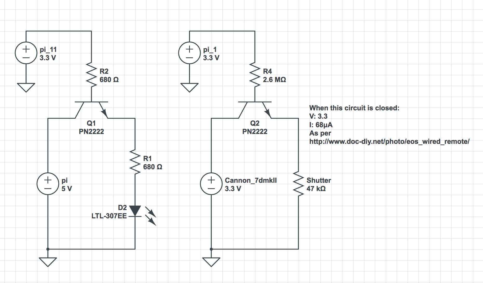
The schematic on the left is what I prototyped using an LED and the on the right is the same (?, we'll get to that) connected to the camera in place of the LED. The LED scenario worked fine, which was exciting, the camera... did not, regardless of the value of R4 - I started with a resistor I believed to be correctly calculated (2.6MΩ) and worked down in resistance until I was using no resistor, the shutter never fired. I've tested all the components and swapped them around diligently checking they all work and are connected correctly.
There are two major differences I can think of, if you understand these and can help confirm and explain, that'd be great. If you spot something else that is the cause of my problems, that's great too.
I can think of:
1) The grounds on the RHS aren't actually the same, one is the camera and the other is the pi. So I'm essentially connecting two circuits via the transistor, whereas on the LHS, I used the pi's + and gnd pins to create power the LED circuit, meaning this is a common ground? Does this make a difference? What should I be doing to connect two circuits in such a way?
2) The current in the camera circuit is very low, 68μA, maybe this isn't enough to cross the transistor C to E (way out of my depth here :) )? Details on the camera circuit can be found here: http://www.doc-diy.net/photo/eos_wired_remote/


