0
\$\begingroup\$

I am working on Intel Galileo board and using its one ADC pin (A5) and one digital GPIO pin (pin 8).

I am switching a relay from GPIO pin and using ULN2003A for isolation and LM60 temperature sensor attached to ADC.I have given power to ULN2003A IC from board only.

Now the problem is when GPIO pin is logic 0 (relay is open) ADC output at room temperature is 125 but when GPIO is logic 1 (relay is closed) ADC output increases to 127.

To debug it I have done below permutations:

-I disconnected relay from isolation IC (ULN2003A) then there is no change in the ourput of ADC (it remains constant).

-I have used electro-mechanical relay and solid state relay but having the same problem.

-I measured voltage with relay connected when GPIO is logic 0 (relay is open) is 4.95V but it drops down to 4.93 when GPIO is logic 1 (relay is closed).

-When a separate power is given to isolation IC (ULN2003A) (from another power source) it works perfectly (ADC output remains constant).

Schematic is below:
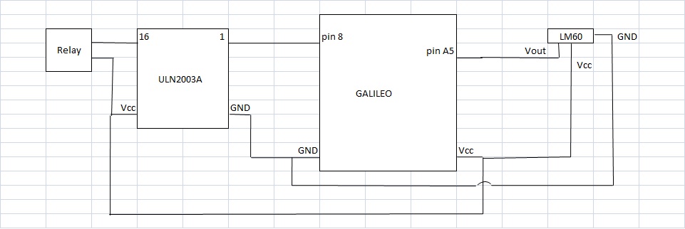
enter image description here

I am unable to understand why ADC output is changing with switching of relay.

\$\endgroup\$
5
  • \$\begingroup\$ If you share a schematic of your circuit, it will be much more clear how you have things connected. \$\endgroup\$
    – The Photon
    Commented May 6, 2015 at 5:22
  • 3
    \$\begingroup\$ Most likely reason: The current draw of the relay is causing your power supply voltage to sag, and the lower power supply voltage is causing the reference voltage of the ADC to change. \$\endgroup\$
    – The Photon
    Commented May 6, 2015 at 5:24
  • \$\begingroup\$ @ThePhoton I have updated schematic of my circuit \$\endgroup\$
    – Saad Rafey
    Commented May 6, 2015 at 6:45
  • \$\begingroup\$ How much current does the relay draw? \$\endgroup\$ Commented May 6, 2015 at 8:41
  • \$\begingroup\$ @WhatRoughBeast electro-mechanical relay is drawing 30mA and solid state relay is drawing 6.5mA \$\endgroup\$
    – Saad Rafey
    Commented May 6, 2015 at 8:52

1 Answer 1

3
\$\begingroup\$

It looks like the Galileo uses the 5 V power supply as the reference voltage for its ADC (see p. 18 of the schematic).

When you close your relay, the extra current draw is causing your 5 V supply voltage to droop by 0.4% according to your measurement.

1 count of an 8-bit ADC is 0.39%. (The ADC is actually a 10-bit part, but maybe the software interface is throwing away two LSBs to give you an 8-bit reading)

It looks like the voltage droop is also affecting the ADC reference, and causing 0.4% error in all ADC measurements.

To fix this, figure out where the power droop is coming from and improve that part. It could mean getting a new wall wart, or it could just mean using thicker (or shorter) wires somewhere in your system. Or it could mean using separate power supplies for the Galileo board and the relays.

\$\endgroup\$

Your Answer

By clicking “Post Your Answer”, you agree to our terms of service and acknowledge you have read our privacy policy.

Not the answer you're looking for? Browse other questions tagged or ask your own question.