Why is the Iz max given before Iz min in this zener diode catalog? If you look at the list of diodes at the bottom, you can see that the maximum test current is given first. Is there something particular or it's just provided this way?
2 Answers
Test currents relate to impedances stated to the right of these figures. For instance, for the 1N5221 there are two test currents listed and these are 20 mA and 0.25 mA and these relate to the maximum dynamic impedances stated in columns to the right (30 ohms and 1200 ohms). Nothing perculiar about this at all.
Those test currents ARE NOT \$I_{ZMAX}\$ or \$I_{ZMIN}\$.
The test currents are \$I_{ZT1}\$ and \$I_{ZT2}\$: -

-
\$\begingroup\$ Is there any way to find the Iz max and Iz min? \$\endgroup\$ Commented May 16, 2015 at 9:22
-
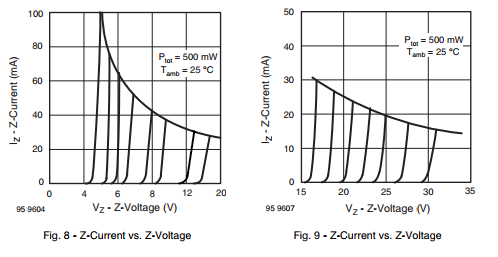
\$\begingroup\$ Izmax is max zener power/ zener voltage i.e. 0.5 watts/2.4 volts = 0.2A except it's a bit more complex because at higher currents the zener voltage will rise so look at figure 8 in the data sheet - this shows a slope and the power limit is implied by the curve. You can also use this to predict what the zener voltage will be at lower currents (Izmin). \$\endgroup\$– Andy akaCommented May 16, 2015 at 9:43
-
\$\begingroup\$ Also some dataheet (see BZX85) show the maximum admissible current (vishay.com/docs/85607/bzx85.pdf) \$\endgroup\$ Commented Sep 22, 2017 at 16:00
Just look into that manual. There are these two graphs for Z-Current vs. Z-Voltage on page 4. You can there easily see that Zeners with higher Vz are more variable in ratio of Vzm:Vz which means they are also differenty variable in theirs resistance.
It shows not every possible Vz, but see that difference in V variability for Vz like :
- Vz=30V at Izt1=4.2mA but Vzm=31.5V at Izm=16mA (Ptot=500mW at 25°C).
- Vz=4.7V at Itz1=20mA but Vzm=5V at Izm=100mA (Ptot=500mW at 25°C).
Find on that graph that Izt1 and Izt2 values (Vz=4.7V at Itz1=20mA and where is than Itz2=0.25mA). They are just near that place where is Zener-diode opening for that theoretical Zener-voltage. On that place is the resistance changing at most. That dynamic resistance is than good to show how exactly is non-linear resistance changing i.e. for sine current (AC) which goes from -Im to +Im all the way over Izt1 and Izt2. Dynamic resistance is close to difference or derivation. It is just good for comparison of two diodes. If two diodes has at same Izt (and same Vz) its dynamic Zz smaller it is also worse Zener-diode (once again see values for small Uz and large Uz) while than Zz goes slower to 0. The same for values of Zz at Izt1 and Zz at Izt2. For two different Uz or Itz it is more complicated to compare values of Zz at Itz while its origin (as ratio Uz/Izt) is somewhere else. For lower ratio (asi it is called impedance or resistance) Uz/Izt is than not necessarily lower dynamic Zz worse.

