0
\$\begingroup\$

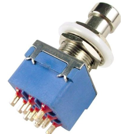
So I currently have a 9 pin switch, that looks like this: enter image description here
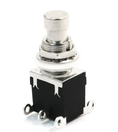
And the project I'm doing calls for a 6 pin switch like this: enter image description here
I'm kind of an electronics newbie and I was wondering if I could just use the 9 pin switch instead of the 6 pin. Would it be a massive problem and is not possible at all or could it work out?

All advice is appreciated, thanks for everything. :D

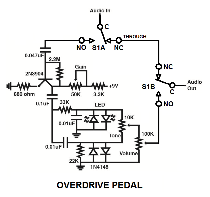
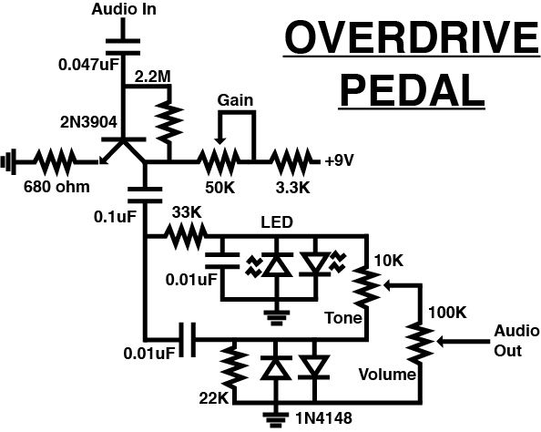
Here's the schematic: enter image description here
\$\endgroup\$
4
  • \$\begingroup\$ Do you happen to have datasheets for both of these that you could link to? The connectors are different; would that pose a problem for you even if the switches can be made to be functionally identical? \$\endgroup\$
    – nanofarad
    Commented Jun 4, 2015 at 23:20
  • \$\begingroup\$ Here are the links to them, I hope it helps: amazon.com/Sonline-6Pins-Momentary-Switch-Guitar/dp/B00X9HXFEO/… \$\endgroup\$
    – HLatfullin
    Commented Jun 4, 2015 at 23:23
  • \$\begingroup\$ The other one: amazon.com/gp/product/… \$\endgroup\$
    – HLatfullin
    Commented Jun 4, 2015 at 23:23
  • \$\begingroup\$ What are you planning to use it for? \$\endgroup\$
    – Andy aka
    Commented Jun 4, 2015 at 23:32

2 Answers 2

0
\$\begingroup\$

The DPDT switch is momentary, while the 3PDT switch appears to be alternate-action, so they're not compatible in terms of physical actuation.

From your schematic there's no electrical toggling going on, so you'll need an alternate-action switch, wired like this:enter image description here

\$\endgroup\$
5
  • \$\begingroup\$ Yep, missed that bit. \$\endgroup\$ Commented Jun 4, 2015 at 23:41
  • \$\begingroup\$ So the 6 pin won't stay in place? It won't keep the circuit running after pressure is released ? \$\endgroup\$
    – HLatfullin
    Commented Jun 4, 2015 at 23:43
  • \$\begingroup\$ @HLatfullin: Correct. \$\endgroup\$ Commented Jun 4, 2015 at 23:47
  • \$\begingroup\$ @HLatfullin: From the switch's point of view, that's right. However, your project may have circuitry which toggles every time the switch is pressed, so it's impossible to say for sure without a schematic. \$\endgroup\$
    – EM Fields
    Commented Jun 4, 2015 at 23:49
  • \$\begingroup\$ I put the schematic there now \$\endgroup\$
    – HLatfullin
    Commented Jun 4, 2015 at 23:55
0
\$\begingroup\$

As a minimum you should beg or borrow some kind of continuity tester that can confirm which connectors on the switches are electrically connected in each (usually 2, sometimes 3) mechanical state. A continuity tester can be a VOM set to measure resistance, a battery and a light bulb, or a battery and a buzzer. You need to identify which pairs of connectors are "normally open" or "normally closed" since this characterises a switch's function. The other electrical characteristic of a switch is its maximum voltage and current ratings that should not be exceeded; you have to find where these are specified because you cannot measure them. It would be dangerous to use a switch intended for a low-current low voltage circuit in a mains voltage power circuit.

\$\endgroup\$

Your Answer

By clicking “Post Your Answer”, you agree to our terms of service and acknowledge you have read our privacy policy.

Not the answer you're looking for? Browse other questions tagged or ask your own question.