1
\$\begingroup\$

I have a AM/FM radio board I found and am trying get playing through a small speaker. The other components were missing so I don't know how this connects to the rest of the system which had a CD player, tape deck and the like.

The board has a single set of input wires pictured below.IO Wiring
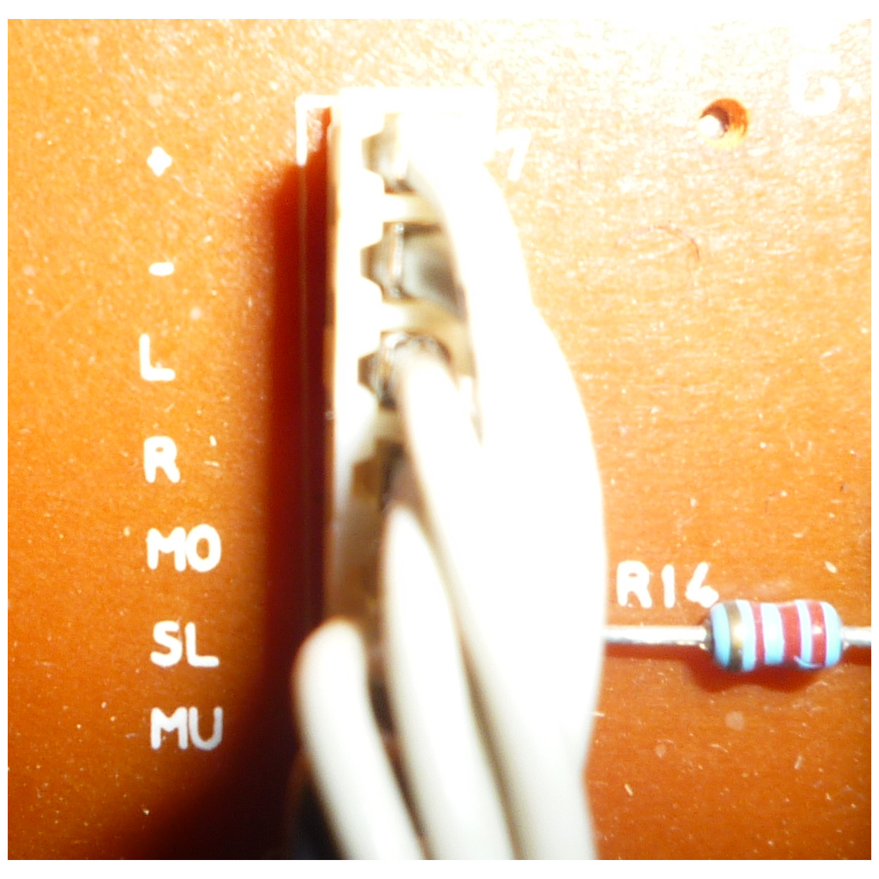
The on board chip is a Toshiba TA8167N which I have found runs on 3 volts and have managed to power. Now I am trying to figure out what is required to connect to the speaker.

As there is only a single out for L and R which connect to the 'R-Out' and 'L-Out' pins on the chip I'm not sure how to complete the circuit. From reading around it looks like I need an 'R-Ret' and 'L-Ret' respectively to complete it but there is no wiring for this available.

I think SL connects to the Stereo LED but I can't follow the MO or MU to the chip as the connections sit under the tuning wheel.

EDIT:

PCB picture added.
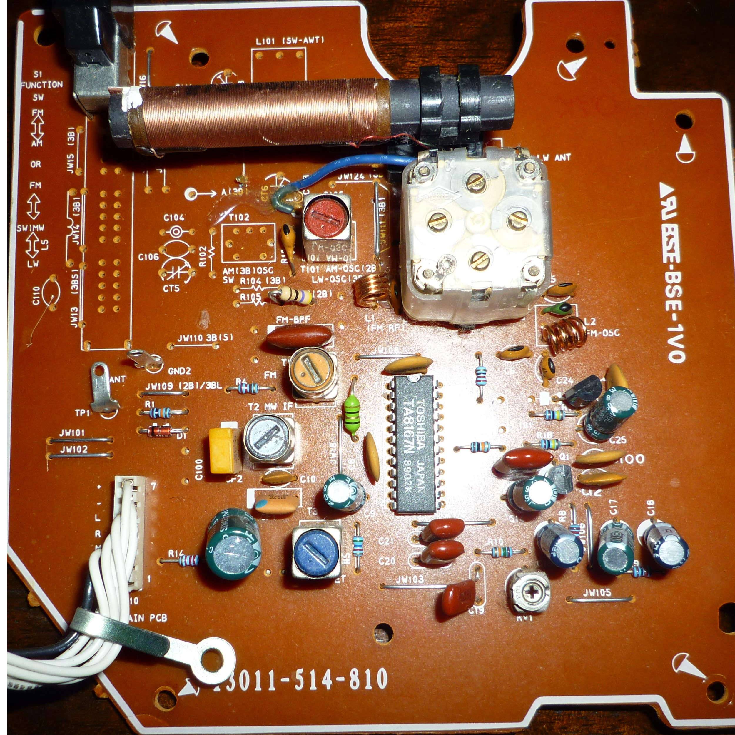
enter image description here

\$\endgroup\$
2
  • \$\begingroup\$ A radio has an RF aerial input. L, R, Mo (Mono), and Mu (multiplex) are all outputs. Ther's no evidence here that you need any more components, but if you do, a closeup of a PCB isn't sufficient to answer the question. You need to provide a schematic. \$\endgroup\$
    – user207421
    Commented Jun 20, 2015 at 2:18
  • \$\begingroup\$ I've looked for a schematic. Board Number is 13011-514-810 but with no success which is why I posted the link to the micro controller as it was all I had. Maybe my question was phrased poorly. As I have a single wire out for say the left speaker I'm not sure how this works going to a speaker where I require both positive and negative wires. \$\endgroup\$
    – EnE_
    Commented Jun 20, 2015 at 2:27

1 Answer 1

1
\$\begingroup\$

The Toshiba TA8167N has single-ended outputs -- the return for both L and R outputs is the GND pin of the chip (pin 9). Is pin 9 connected to the "-" pin of the connector you showed?

Tuner chips like these are rarely connected directly to a speaker. More typically, the tuner chip output pin is connected through a 4.7 uF capacitor (as shown on p. 8 of the TA8167N datasheet) to a "volume knob" connected to an audio amplifier such as the Texas Instruments LM386N-4, as shown on p. 6 of the LM386N-4 datasheet.

The LM386N-4 and many other audio amplifiers are also single-ended -- the return is the GND pin of the chip. You'll need 2 such audio amplifiers (or a "dual amplifier"), one to amplify the L signal and the other to amplify the R signal.

(Could you show a photo of the entire PCB? Perhaps your PCB already includes a volume knob and perhaps even an amplifier).

\$\endgroup\$
2
  • \$\begingroup\$ Thanks for the info, I have added the full PCB. The volume knob was definitely elsewhere. \$\endgroup\$
    – EnE_
    Commented Jun 20, 2015 at 4:27
  • \$\begingroup\$ Also, pin 9 is connected to the '-' pin of the connector \$\endgroup\$
    – EnE_
    Commented Jun 20, 2015 at 7:21

Your Answer

By clicking “Post Your Answer”, you agree to our terms of service and acknowledge you have read our privacy policy.

Not the answer you're looking for? Browse other questions tagged or ask your own question.