This is a "Radio Control servo" or just perhaps "servo" but it is NOT a "servomotor" in the normal sense. It includes a basic servomotor but also includes a controller, which is more than just a servomotor AND makes the requirement different.
You need to
The normal "hack" to make an RC servo run continually as if it was only a geared motor is two fold.
Mechanical: The end stop(s) which limit travel are removed. Sidecutters are usually your friend with plastic geared RC servos.
Electrical: You need to understand how an RC servo works. Details below - the internal position feedback pot is replaced by two fixed resistors. The controller thinks the motor is at a fixed position and drives towards it forever.
Here is a Flickr photostream showing a continuos servo modifcation
I pointed it to that page as it has a number of links there. You can go back a few photos in the sequence to see the resistor fitting I mention above. I've included some similar links below.
It seems likely that you do not understand the requirements for driving an RC srevo OR that the hack has been severe.
Your servo should have at least leads.
If not, please advise. If so then this is how it is intended to be controlled.
Power is applied to the Power and ground leads.
A pulse train that meets the manufacturers specs is applied to the signal lead (relative to the ground lead). Pulse train specs vary between manufacturers but typically a 1 mS pulse indicates hard "left" a 1.5 mS pulse indicates centred and a 2 mS pulse indicates hard 'right". See page 5 in this Cytron servo controller manual.
If you remove the servo feedback pot and replace it with two equal value resistors then the electronics 'thinks' that the motor is at mid position.
If you command it to go left it will seek leftwards forever.
If you command it to go right it will go rightwards forever.
If you command it to centre it will 'see' the two resistors set at midpoint and will stop (as it appears to be centred). You will probably need to "fine tune" the pulse width sent to exactly match the resistor set point to achieve stopping.
The problem: The control pulses do not control the speed - only the position. As you are 'telling it' that the position is wrong (not enough left or not enough right) it will hurry left or right as fast as its motor will carry it. You can probably alter motor speed somewhat by varying the power supply voltage within approved specifications but this is liable to be less than satisfactory.
There is a way to control speed after a fashion but it also may be unacceptable.
Motor position is updated about every 20 mS.
Usually you will be outputting either a 1 mS pulse then a ~= 20 mS delay to go "left" or a 2 mS pulse followed vy an ~ 20 mS delay to go "right". (Total time for a command cycle is flexible, only pulse width matters.
Instead, send a "right" command, wait a small while and then send a "centre" command. The motor will advance a small distance and then stop. Repeat. The motor will incrementally rotate at its single fixed speed but with pauses between movements.
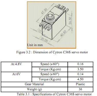
The table below comes from this BE report It states that the 36s rotates at 0.96 s/rev at 4.8V and 0.84 S/rev at 6V. Close to 1 second/rev in both cases. Voltage variation is not going to help much. However, if you send say 60 command sequences per second the motor will have rotated about 360/60 = 6 degrees during that time. If you send right-centre-right-centre-right ... continually at 60 sequences per second the motor can be expected to run at about half speed. There may be a rate that is too fast for the controller - possibly not. You may have to use
"right - pause X mS - centre - pause Y mS - right - ..." to get consistent speed reduction.
The problem (or a problem) with this system is that the result will be jerky, and more so as the speed is reduced with longer off periods. There are several ** possible** solutions.
(1) Increase command rate. The maximum pulse length is 2 mS. The typical interpulse length is ~= 20 mS BUT the controller may accept far smaller times between commands. You MAY be able to send say 200 commands/second (5 mS between pulse start edges.) If so then you MAY be able to achieve "smoothish" control over a reasonable speed range. Experimentation is easy - Just use the right- pause - centre pause sequence as above and vary the pauses. Right = (say) 1.1 mS pulse. Left = (say) 1.9 mS pulse. Centre ~~ 1.5 mS pulse BUT you will need to find the exact range of values that allows stopping.
Note that starting and stopping the motor in this way will almost certainly reduce available power as the motor will take a finite time to reach operating speed range.

(2) Throw away the servo's internal controller. The servo is a geared motor with additional electronics. The electronics are not made to do what you are trying to do with them. Removong the Rpulse decoder and PWming the motor directly would work for you. There will be an H bridge driver in there Bbut it may be inside the decoder IC. You will want to find somebody who understands what is required.
(3) Buy a geared motor. You are attempting to reinvent a geared motor. These are available at hobby shops and elsewhere. Also lurking inside every cordless screwdriver (usually no H bridge). A geared motor plus drive electronics plus PWM will probably do what you want easier and better.


