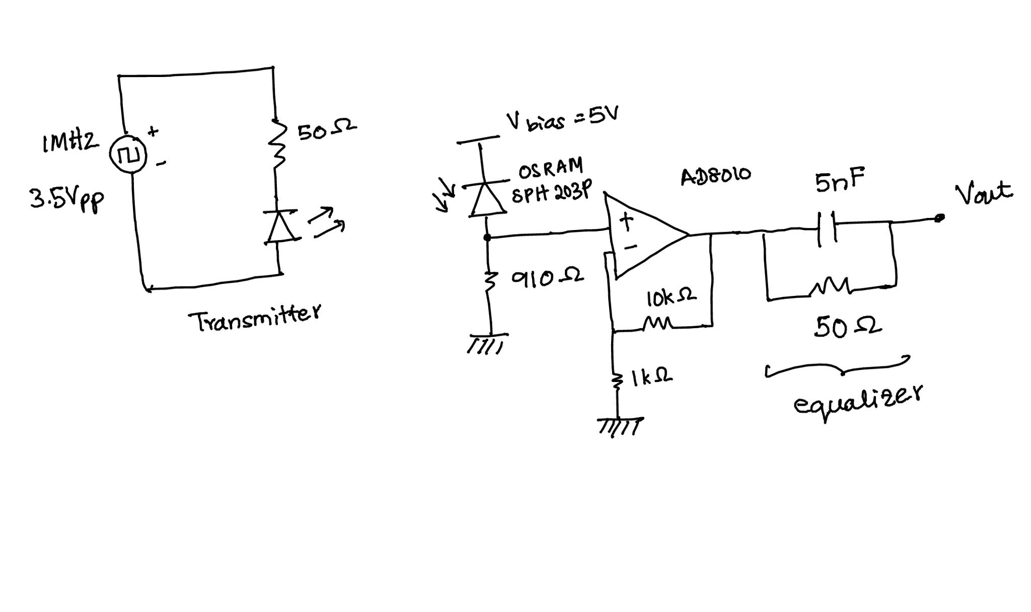
I am currently working on a VLC project to build a VLC receiver. I attached a schematic of the circuit I have designed. The circuit on the left is the transmitter sending a square signal at 1 MHz using the CREE RGB LED. I am receiving the signal at the other end using a OSRAM photo-diode and passing it through front end amplifier to amplify the received signal. Later its sent through a 1st order equalization circuit, to fix my distorted square wave signal. I amunsure whether my equalization circuit is correct since I do not see any change in the signal when I implement this circuit. I also experience a ringing (overshoot and oscillations to settle down) in the output waveform. Could you please help me understand the how I can equalize to get a better response to get a cleaner square wave and also to reduce the ringing in my circuit. Any response is much appreciated.

2 Answers
As shown (with no output load) the signal at Vout will not be affected much at all by your RC "equalizer". If you were to place a low value resistive load (maybe 100 ohms or lower) from Vout to ground you should then see a better response. If the added load doesn't give a satisfactory square wave then you might even consider placing a simple high speed comparator circuit after the AD8010. To limit the frequency response of the AD8010 (and reduce oscillations etc.) also consider placing a very small value capacitor across the 10k, (low pf range). The added capacitor would help to give a smooth pulse to the comparator,(if used), then the comparator can further square up the signal. In addition be sure to use bypass capacitors at all power pins.
If you are only interested in a digital (binary ) signal - I.e. the output should be either high or low, a simple Schmitt trigger circuit would work well for this. It would produce a square signal at its output from the photodiode output.
