2
\$\begingroup\$

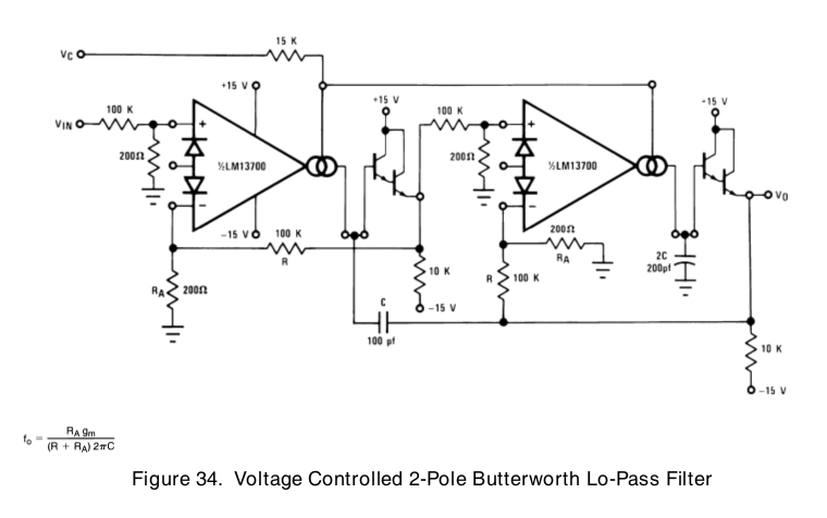
In the Texas Instruments datasheets for the LM13700 Transconductance Op Amp (as well as the earlier National Semiconductor versions) there's been an application note showing a voltage-controlled 2 Pole Butterworth low pass filter (in the TI datasheet this is shown in Figure 34 on page 15):

enter image description here

I'm using that filter but would like a symmetrical high pass filter (likely using the same RC values as the low pass). I basically need a balanced pair of voltage-controlled low and high pass filters.

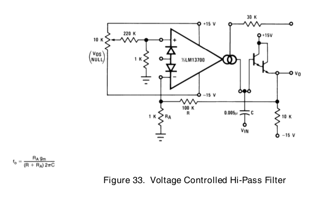
Does anyone know either of an existing schematic (in a book or online) or otherwise how I'd design an equivalent voltage-controlled 2-Pole Butterworth high pass filter? I've tried diagramming it and can't figure out, apart from the obvious bit of connecting the output of the first stage to the second, where the feedback is between stages. This is complicated by the fact that the high pass filter (Figure 33) uses the juncture between the output and buffer input (pins 5 and 7) as the source input:

enter image description here

I suppose the easiest way to approach this would be to ask: what changes would I make to the existing low-pass filter (Figure 34) to make it high-pass? This would seem straightforward were it not for my own limitations. [Oh, and apologies by way of explanation: I'm not an engineer but likewise not exactly new to analog circuitry, but I am to use of transconductance op amps.]

If it's any help, this is for audio range frequencies with a +-9VDC supply.

Thanks very much for any assistance.

\$\endgroup\$

2 Answers 2

1
\$\begingroup\$

I assume that you are not forced to use the structure as shown in your diagram (for lowpass filters)? In the following, I give you the link to one of the classical inventory articles on OTA filters:

http://class.ece.iastate.edu/vlsi2/docs/Linked%20Publications/1985-03-ICADM-RG.pdf

With reference to Fig. 7 in this paper, I recommemd to choose on of the structures which can be used for lowpass or highpass second-order functions. Formulas how to control the various parameters are also given.

\$\endgroup\$
1
  • \$\begingroup\$ No, I'm not actually forced to use the structure in Figure 34, but part of the reason I'm choosing this approach is to learn how to use OTAs to the problem. I do need the high and low pass filters to be symmetric (i.e., have identical or very similar characteristics). Regarding the solutions presented in the paper you referenced (thank you), as I mentioned I'm not an engineer by trade and am unfamiliar with going from formulae to schematic. \$\endgroup\$ Commented Nov 17, 2015 at 23:58
1
\$\begingroup\$

You can use filters subtractively....

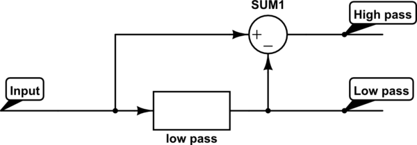
Take your original signal and produce the low pass output version using the circuit in your question. Then, take your original signal and subtract the low pass output from it. What you are left with (as a new signal) is the high pass version.

So what you get is two outputs; one is low-pass with a cut-off frequency at (say) 1kHz and the other is a high pass with cut-off frequency also locked-in to 1kHz - if you lower the cut-off frequency of the LP filter then the HP also lowers its cut-off.

schematic

simulate this circuit – Schematic created using CircuitLab

\$\endgroup\$
7
  • \$\begingroup\$ Andy, please can you demonstrate how and why your scheme gives a highpass response (same cut-off and same characteristic)? \$\endgroup\$
    – LvW
    Commented Nov 17, 2015 at 14:43
  • \$\begingroup\$ @LvW if the input is a low frequency then subtracting the LP output from the input will produce very little signal. If the input is a high frequency then the LP output will be tiny and the HP output will be largely unaffected. Clearly the LP output should not be an inverting type for the subtraction to work else, it's addition. I've used this technique in digital filter design and I believe a biquad analogue filter uses this method (albeit in a feedback loop) for producing the HP output. \$\endgroup\$
    – Andy aka
    Commented Nov 17, 2015 at 14:54
  • \$\begingroup\$ Also you can make a notch filter by adding an LP and HP output so the principle is well-known. \$\endgroup\$
    – Andy aka
    Commented Nov 17, 2015 at 14:58
  • \$\begingroup\$ Andy, I agree to your qualitative explanations; that means: A transfer function COULD be produced that has a highpass characteristic, BUT: The lowpass gain must be unity, otherwise this method does not work. And more than that, the rising highpass slope is of first-order only. This can be simply verified mathematically. Hence, I don`t recommend this method because the questioner needs two "symmetrical" responses. \$\endgroup\$
    – LvW
    Commented Nov 17, 2015 at 15:44
  • \$\begingroup\$ @LvW Yeah the slope of the HP is not the same rate as the LP. \$\endgroup\$
    – Andy aka
    Commented Nov 17, 2015 at 15:59

Your Answer

By clicking “Post Your Answer”, you agree to our terms of service and acknowledge you have read our privacy policy.

Not the answer you're looking for? Browse other questions tagged or ask your own question.