2
\$\begingroup\$

Some designs have parts that may lack a reference designator because they never appear on the schematic. Examples include:

  • Battery holders
  • PCB-mounted (soldered on) fasteners such as solder-nuts
  • IC sockets
  • Jumper wires on a single sided board (if they haven't been backannotated to the schematic, that is)
  • Plugin modules such as keypads and LCD modules (if they haven't been given a schematic symbol)
  • Heatsinks

Are there any standards or conventions for how these are listed in a Bill of Materials for a circuit board?

\$\endgroup\$

3 Answers 3

4
\$\begingroup\$

The best way to handle parts that don't appear on the schematic is to fix the schematic so that they appear. If you don't, you'll constantly be manually fixing the BOM that is automatically generated by your tools.

This applies to all the parts that belong to the immediate built board assembly. At the least, these are the parts that get soldered or otherwise mounted to the board. If the built board is part of a larger assembly, then the BOM for that assembly will show the built board as a single line item, and it can call out screws, nuts, standoffs, etc, for mounting the board into the larger unit.

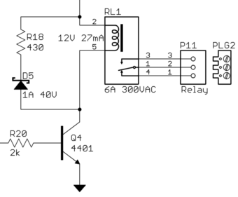
And yes, this applies to sockets too. For example, here is a snippet of a larger schematic for a real commercial product that exists in the company's formal manufacturing database:

P11 is a Phoenix Contact connector that accepts a plug with screw terminals. Only P11 actually gets mounted to the board, but there always needs to be a plug with the board. That's what PLG2 is. It is there primarily for the purpose of automatically appearing on the BOM. In this case I think showing it on the schematic is also a nice visual reminder that the board comes with a screw-terminal plug.

\$\endgroup\$
2
\$\begingroup\$

In general, what I have seen at slightly larger more organized companies is that they try to put all the BOM items on the schematic. The reason is that the BOM is generated using the EE CAD. So the BOM will be more complete if all those things are included.

The details of how you do it need to be tailored to your specific CAD tools and manufacturing data management software.

I would definitely try to capture anything that is installed on the circuit board in the schematic somehow. If necessary, you can assign it a reference designator. No harm. For plugin modules, it might be a judgement call. If you have a hierarchical BOM, the module could be a subassembly under the PCB BOM.

I am generally not dogmatic about these kind of things. The key is to find a workflow that reduces the chance of errors (wrong part, failure to order parts, etc).

\$\endgroup\$
2
  • \$\begingroup\$ I have never seen a schematic symbol for an IC socket or a battery holder, and oftentimes heatsinks don't seem to get one either, even when you're looking at the schematics in a commercial product's service manual. \$\endgroup\$ Commented Dec 27, 2015 at 18:27
  • \$\begingroup\$ @ThreePhaseEel, OK, I agree with you about the IC socket. The heatsink NEEDS to be on the BOM otherwise it will not be ordered. But there is usually an ME BOM as well as an EE BOM. It could go on the ME BOM. But if it is on the EE BOM, I would add it to the schematic. As far as the socket goes, they are usually only used for debug during development. So I can understand not putting in the schematic. You just need to have a process that ensures nothing is overlooked. \$\endgroup\$
    – user57037
    Commented Dec 27, 2015 at 18:47
2
\$\begingroup\$

At my company, we have strong opinions on how to do this from both the mechanical and electrical teams. The detenté we have settled on is that for primarily EE-centric assemblies (I.e. PCB assemblies), we will add mechanical components to our docs to centralize BOM generation.

As we use Altium, the simplest method is to toss parts on the schematic, and set them to 'Mechanical'. They are then not included in electrical rule checking, nor are they present during layout -- they only appear on the BOM.

Most of these items are placed on the last page of the schematic (revision history) and include things like fasteners, the blank PCB itself, conformal coat, threadlock, heat sinks, etc. The blank PCB gets a PCB? Refdes, and we decided on MP? for the others -- no conflict with traditional reference designators and all parties understand what they mean.

With this method, the EE team owns that assembly, and generates (automatically) BOMs that include everything we need, the MEs need and the systems team needs.

As far as symbols go, the PCB placeholder is a simple square and one of my artful colleagues made representations of various fasteners, Etc that we place there.

Finally, just to throw some fuel on the fire, we put our plated mounting holes on the schematic only (not on BOM) so that we can see what their electrical connectivity is.

\$\endgroup\$

Your Answer

By clicking “Post Your Answer”, you agree to our terms of service and acknowledge you have read our privacy policy.

Not the answer you're looking for? Browse other questions tagged or ask your own question.