1
\$\begingroup\$

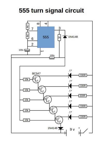
I stumbled upon a very badly drawn circuit on the interent which must be good . I have not been able to figure out how a series of transistors work in this circuit. It is depicted below.

enter image description here

When this circuit powers, the leds turn on and stay on one by one until the last led is turned on, and then they all go off and the cycle starts over again. My question is in regards to if someone could explain to me why this behavior happen with the transistors. I am not sure how an astable pulse to this array of transistors would cause this cascading behavior.

\$\endgroup\$
5
  • \$\begingroup\$ Have you simulated it yet? \$\endgroup\$ Commented Jan 1, 2016 at 20:02
  • \$\begingroup\$ @IgnacioVazquez-Abrams, yes. I could not get it to work though. But here is the link to it working instructables.com/id/Turn-signal-using-555-timer/?ALLSTEPS \$\endgroup\$ Commented Jan 1, 2016 at 20:04
  • \$\begingroup\$ Clue: it may be a high/low pulse at pin 3, but after the RC network it's not a pulse. What does the waveform look like there? \$\endgroup\$
    – pjc50
    Commented Jan 1, 2016 at 20:08
  • \$\begingroup\$ @pjc50, I'm new to electronics, so I'm sort of guessing, but would it be more like a spike? \$\endgroup\$ Commented Jan 1, 2016 at 20:10
  • \$\begingroup\$ Here's a valuable tip free of charge: Never, ever assume that a badly-drawn circuit on the internet "must be good". \$\endgroup\$ Commented Jan 1, 2016 at 21:11

3 Answers 3

1
\$\begingroup\$

Improved LED Sequencer Circuit

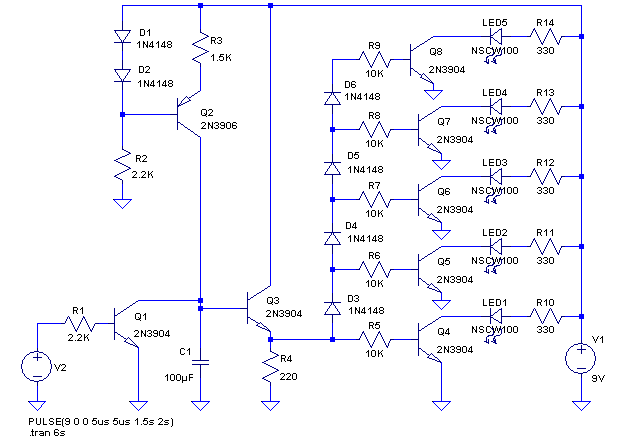
This circuit has improvements over the posted circuit with the addition of a few more components. Still all simple components!! I did not include the astable oscillator in the simulation but that can easily be built with a 555 or a couple more transistors, resistors and capacitors.

enter image description here

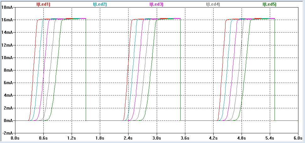
A current source keeps the voltage ramp linear. An emitter follower buffers the waveform to the threshold diode stack and all transistors switch the same current levels to each LED.

enter image description here

The net result of this is that timing steps of the LEDs turning on are much more even and the timing parameters are easily adjusted to get desired timing, whether this be for a turn signal sequencer or for a light sabre flash up.

\$\endgroup\$
2
\$\begingroup\$

This circuit works by creating an exponential R/C ramp voltage to the base feed resistors of the stack of transistors. Each transistor going up in the stack turns on at a higher voltage on the ramp due to the emitter of each being referenced to the base of the proceeding transistor.

The circuit design as shown however has some issues:

  1. First off is that the sequencing of the five LEDs all happens within about a quarter of a second and the times are not uniform.
  2. Another problem is that the higher LEDs get successively lower and lower current though them due to the stepping up of the saturated collector voltage on each successive transistor. This will lead to LED brightness variation unless the values of the 330 ohm resistors are weighted accordingly. Current variation as shown is from 14mA down to about 3mA.
  3. The LED current for upper stages in the stack has to flow through the base-emitter junctions of the transistors below it. Some small signal transistors have a maximum specification of allowable base current and this could get to be a problem if higher LED currents are attempted. In this case the lowest transistor base current max is about 27mA and the BC547 is rated up to 200mA so should be OK.
\$\endgroup\$
0
\$\begingroup\$

pjc50 gave you an important clue, but the other thing you need to know is that the turn-on threshold for each transistor is one diode drop (VBE) higher than the transistor below it. The bottommost transistor turns on at about 1.3 V, which is its own VBE drop plus the VF drop of the diode.

That's a terrible schematic diagram, by the way. It uses unconventional symbols for components; it has the output capacitor connected badly; and it lacks reference designators on the components, which would make it easier to talk about them. See this article for some tips on drawing good schematics.

\$\endgroup\$

Your Answer

By clicking “Post Your Answer”, you agree to our terms of service and acknowledge you have read our privacy policy.

Not the answer you're looking for? Browse other questions tagged or ask your own question.