6
\$\begingroup\$

This is a very beginner's question - I apologize if this is some trivial extension of a known practice.

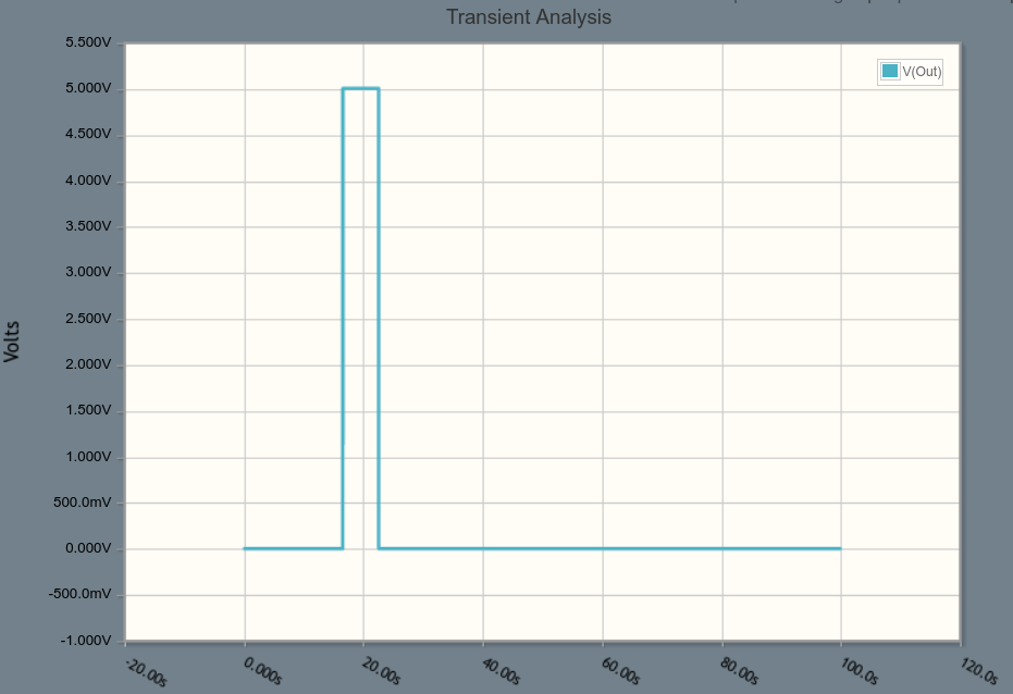
Can I use one 555 timer without any extra transistors/IC to generate a delayed pulse as shown below upon powering up the circuit?

enter image description here

The intended circuit has no buttons or other external triggers. It is activated by being suddenly connected to power (from z-wave smartswitch) and is supposed to:

  • after power up, keep output pin low for ~15 seconds
  • put output pin to high for ~5 seconds
  • finally, put it to low and keep it there forever

This probably can be done easier with two 555 timers but I think that one 555 timer should be able to do it as well. This is also a great learning experience in understanding the mechanics of 555.

\$\endgroup\$
4
  • 1
    \$\begingroup\$ I would look into using the resetbar signal to create the initial delay. As an example, use an RC network to delay the pullup of the resetbar signal after powerup (by ~15s). \$\endgroup\$
    – jbord39
    Commented Jul 13, 2016 at 15:08
  • \$\begingroup\$ @jbord39 wouldn't it require adding a digital IC? Or are you suggesting that reset would play well with the gradually increasing voltage from RC network directly? \$\endgroup\$
    – akhmed
    Commented Jul 13, 2016 at 21:40
  • \$\begingroup\$ It's worth a try; according to the datasheet the timer will start once resetbar=0.7V or more \$\endgroup\$
    – jbord39
    Commented Jul 13, 2016 at 22:14
  • \$\begingroup\$ I see -- this is an interesting idea. CircuitLab does not seem to like it though: it looks like any voltage on resetbar no matter how small is simulated as high digital signal - I guess they want me to use a digital IC here. \$\endgroup\$
    – akhmed
    Commented Jul 14, 2016 at 2:03

2 Answers 2

4
\$\begingroup\$

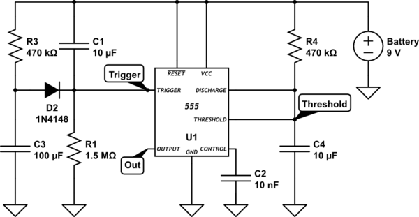
I created the following circuit that seems to be able to accomplish that task with just one 555 and no external triggers.

Explanation of my circuit:

  • The left-side attempts to simulate a delayed trigger pulse.
    • R1-C1 is slowly decreasing the voltage from high to low and manipulates the length of time when output will be on LOW (~15 seconds)
    • R3-C3 is increasing the voltage but slightly slower than R1-C1 so that Trigger voltage dips below 3V but not for long
  • The right-side is a monostable 555 implementation
    • R4-C4 manipulates the length of time when the output would be on HIGH (~5 seconds)

schematic

simulate this circuit – Schematic created using CircuitLab

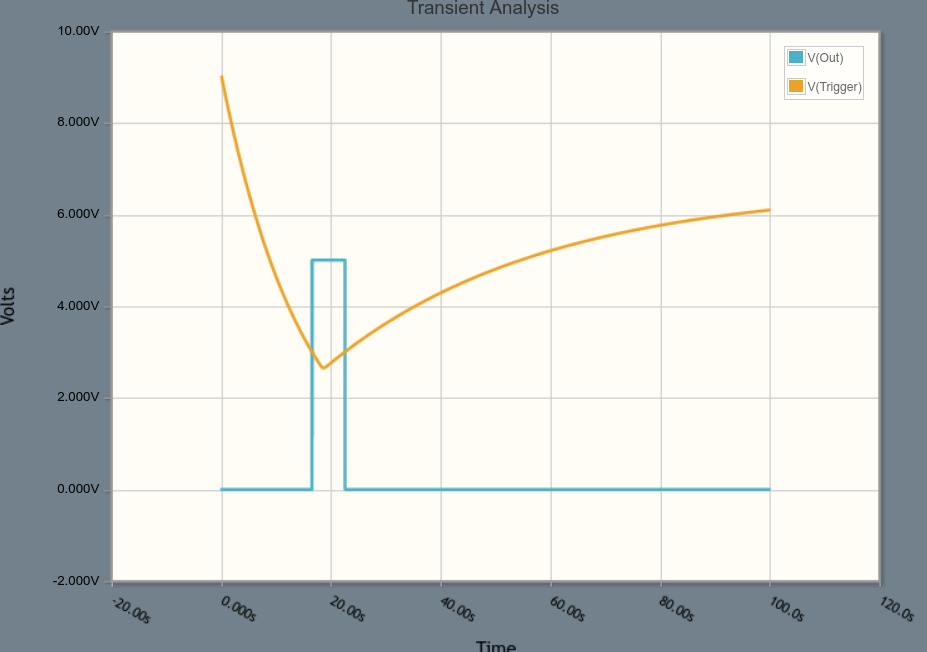
Here are the voltage measurements:

enter image description here

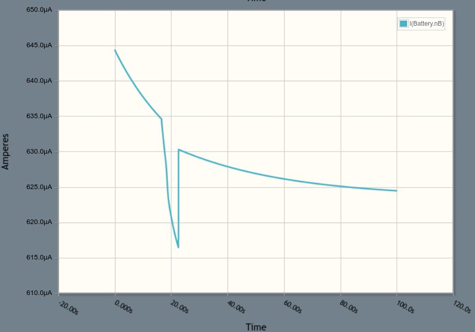
Here are the current measurements:

enter image description here

I think this implementation works but is there an easier way to accomplish that?

\$\endgroup\$
4
  • 1
    \$\begingroup\$ I don't believe so -- the system with the "counterbalanced" RC charge curves is rather clever. I may have to knock one of these together on the breadboard and take a scope to it, if you haven't done so already :) \$\endgroup\$ Commented Jul 13, 2016 at 2:15
  • \$\begingroup\$ Thanks! I did try it on a breadboard and it worked!! R3-C3 needs to be calculated really precisely though! Note that capacitors tend to stay charged after removing power so the circuit shouldn't be used again immediately after powering down (fixed this adding some X megaohm resistors around capacitors to give them some escape route.) \$\endgroup\$
    – akhmed
    Commented Jul 13, 2016 at 2:27
  • 1
    \$\begingroup\$ Clever! However, I believe the balanced R1C1 and R3C3 would be highly problematic, since they have to be close together—the tolerances, voltage/temp coeffs and stability over time of large electrolytic caps will severely limit precision (and thus reliability of the trigger pulse). \$\endgroup\$ Commented Jul 13, 2016 at 3:05
  • \$\begingroup\$ Yep, agreed! It seems to do its best with longer pulses and shorter delays before the pulse -- it seems to accept wider margins. I think I can also add auto-shutdown to it just by placing a large capacitor right at the battery terminal. Electronics is so cool! :) \$\endgroup\$
    – akhmed
    Commented Jul 13, 2016 at 3:55
0
\$\begingroup\$

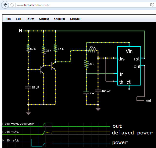
This could work, but there is some voltage ramp at the start of the pulse.

The power is delayed through two common emitter inverters before hitting the 555's RC chains to trigger monostable mode. You want the current drawn by the RC networks to be low enough so that there is no significant voltage drop across the second output resistor of the delay chain.

You will need to tweak the RC time constants to get the delays you want, just simulated as proof of concept.

The other circuit posted is neat but you will need to 'tune' it for it to work; balancing the RC chains (it could not fire at all). If the circuit I posted comes out of tune, it should just cause the initial delay/ pulse width to change; but it will still fire.

schem with sim proof of concept

\$\endgroup\$
1
  • \$\begingroup\$ Thanks. This is very interesting! My initial question asked about a circuit w/o transistors but this is a very educational circuit. My biggest concern is the gradual voltage ramp up though. The output is connected to a rising-edge detector (hence the use of a timer in the first place). Wouldn't the ramp up mess it up? \$\endgroup\$
    – akhmed
    Commented Jul 14, 2016 at 4:10

Your Answer

By clicking “Post Your Answer”, you agree to our terms of service and acknowledge you have read our privacy policy.

Not the answer you're looking for? Browse other questions tagged or ask your own question.