I bought a pack of 5 ICs from radioshack. (74LS00, 74LS02, 74LS04, 74LS08, and 74LS32 to be specific). And I can't see to wire them correctly. I've wired pin 7 to ground, pin 14 to 5V(from an Arduino Uno), and nothing comes out of any outputs. What even worse is if I disconnect ground the led does come on. And by using the Arduino to measure voltage, all of the outputs are on. I've wired this perfectly and even checked with this site to make sure: https://www.facstaff.bucknell.edu/mastascu/eLessonsHTML/Labs/Logic/LabLogic1A.html I've also checked to make sure that pin 7 is indeed ground and pin 14 is indeed high with the Arduino. I just can't figure out why none of it is working. What's even worse is all of the ICs are exhibiting the same behavior. And I've tried two different breadboards, with the same result. Any help?
-
\$\begingroup\$ 1. Are you positive you have the chips correctly oriented (pin 1 is on the side of the chip with the little divot in it)? 2. Are you positive you have a good 5V power source? 3. Are you supplying the correct inputs to get an output (they should not be floating & 7400 is a NAND gate)? You don't need to measure the output voltage, just use a pair of LEDs with series 1k resistors - one going from the output to ground, and the other going from 5V to the output. Only one LED should be on at a time. \$\endgroup\$– Kurt E. ClothierCommented Jan 15, 2016 at 0:24
-
\$\begingroup\$ I'm pretty sure Arduino Uno's come with a goof 5V regulator and pin 1 is on the side of the chip with the divot on it. I'm using this as a pinout map: neoembedded.com/media/wysiwyg/7400.jpg \$\endgroup\$– tjpc3 The RedstonerCommented Jan 15, 2016 at 0:35
2 Answers
Wow, I had to check my calendar to be sure it wasn't 1976.
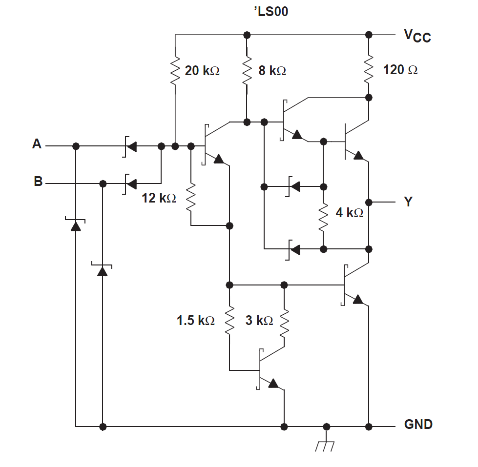
The 74LS family is well past its best-before date. It's a DTL family (pretending to be TTL). As such an 'open' input is interpreted as a logic 1. If you leave both inputs open, and are using a 74LS00, it will do what NAND gates do with two '1' inputs and drive the output low. Ground either of the two inputs to a NAND gate and the output should go high.
In general you will be a lot less frustrated if you always connect every in put to a logic 1 or logic 0, including unused inputs. That will come in especially handy with CMOS (eg. 74HC00) where the inputs can do odd things if you let them float. For TTL families and LSxx, ground or tie inputs high through 1K. For CMOS tie high or low directly or through a resistor.
Schematic of 74LS00 gate (from the datasheet):
-
\$\begingroup\$ LOL, maybe he is learning about digital logic! \$\endgroup\$ Commented Jan 15, 2016 at 0:25
-
\$\begingroup\$ @KurtE.Clothier Hands-on is not a bad way to learn. Except maybe high voltage/high power electronics. \$\endgroup\$ Commented Jan 15, 2016 at 0:26
-
\$\begingroup\$ So ground is considered a logic 0 and open a logic 1? \$\endgroup\$ Commented Jan 15, 2016 at 0:32
-
\$\begingroup\$ Effectively, but don't do that. Tie it through a 1K resistor to +5 for 1. Or to another logic output. \$\endgroup\$ Commented Jan 15, 2016 at 0:37
-
1\$\begingroup\$ Thanks! After some more fiddling with the circuitry I think I understand it now. \$\endgroup\$ Commented Jan 15, 2016 at 1:54
The 74LS series is bipolar TTL - it uses mostly NPN transitors, and its inputs source current. They will therefore appear as logic High when not connected.
To make the inputs appears as logic Low (0), you have to connect them to ground (pin 7 of the chip).

