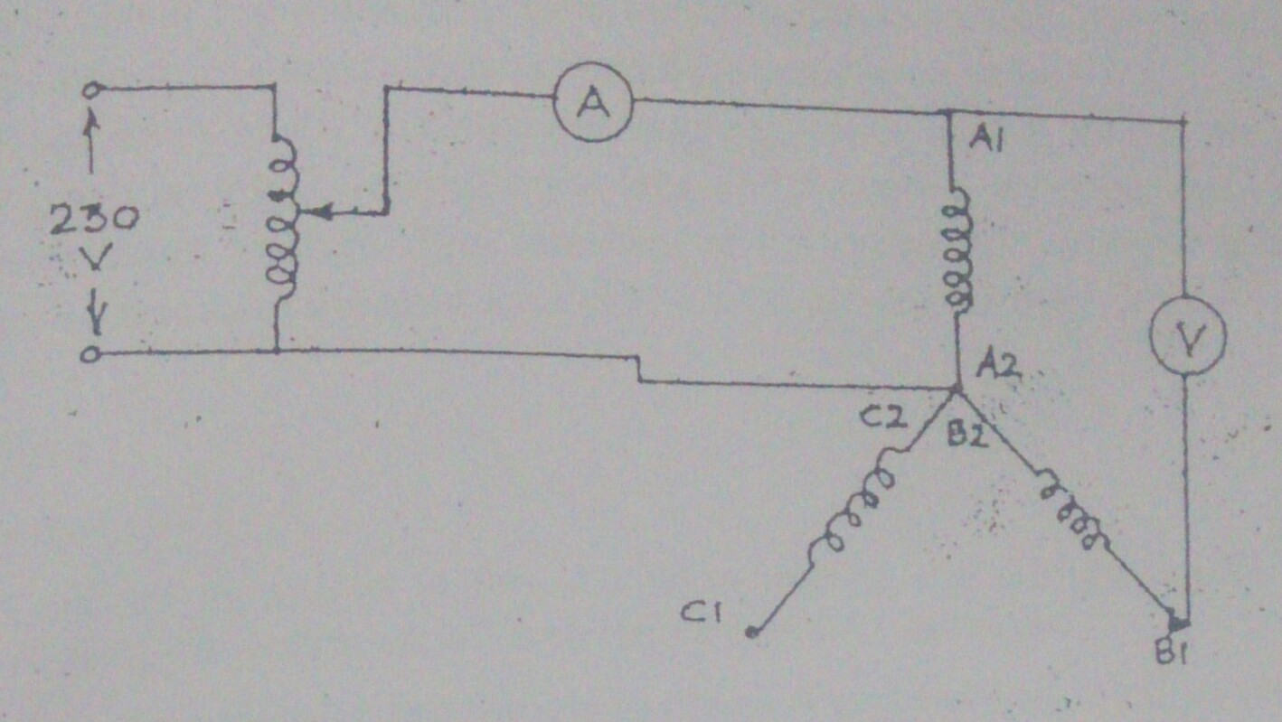
I was performing experiment in the lab of my university. The experiment was supposed to be performed on a squirrel cage induction motor. But I performed it on a three phase slip ring I.M with its rotor short circuited. All the voltages used were AC voltages. I applied 100 V across one terminal of phase(A1) and neutral(N) of a star connected stator winding.
When the polarity was same (i.e. the star point was at A2,B2,C2), the voltage across A1 and B1 came out to be 84 V, which is less than 100 V. My question is: Shouldn't it be more than 100 V because the voltages induced in both the windings are additive in nature or am I interpreting anything wrong?
When we change the star point to A2,B1,C2, then the voltage across A1 and B2 comes out to be more than 100 V. In this case, shouldn't it be less than 100 V?

-
1\$\begingroup\$ You would do well to specify whether the voltages are AC or not. In addition a diagram or two would be useful to helping understand your question. Have the diagram include the excitation points and the measurement points. \$\endgroup\$– Michael KarasCommented Jan 19, 2016 at 14:22
-
\$\begingroup\$ @MichaelKaras I've done that, but still I have not got any responses. I don't know why? \$\endgroup\$– GurpreetCommented Jan 20, 2016 at 14:16
2 Answers
- If the windings in the motor were windings of a transformer, you are probably right - but this is a motor and therefore the two windings in serie are wound in opposite directions and may not be considered as additive. The windings don't share the same iron core position either so the magnetic fields from the different field windings are not 'in line' as they are in a transformer. It seems like you are messuring the input voltage + the induced voltage of opposite polarity from the second winding. Looking forward to any comments
-
\$\begingroup\$ I measured the applied voltage + the induced voltage. I connected the voltmeter as shown in the diagram. \$\endgroup\$– GurpreetCommented Feb 7, 2016 at 3:18
Gurpreet, what you have to remember is, that you diagram of a "Y" connection is only a schematic representation. The windings for phase "A" would physically be 4, or more poles, evenly spaced around the circumference of the stator, each one alternating, N - S - N - S etc. The same would apply to phases "B" & "C", all arranged so that all poles alternate, N - S - N - S, and they "lay alongside" one another. If you pass a voltage through say phases "A & B", and the two poles are alike, the opposing magnetism will affect the voltage one way. Passing the voltage through the coils so they attract, will affect the voltage the other way. Hope this makes sense !
