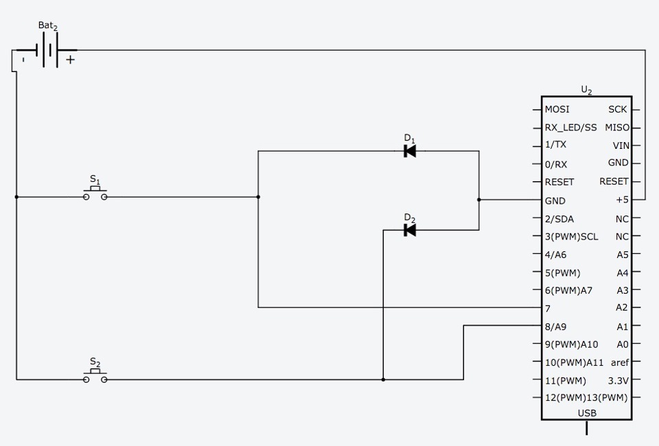
I'm trying to determine if this circuit is going to work exactly as I think:

Expected behavior is:
- When we press S1, arduino turns on and digitalRead(7) will give us HIGH value (INPUT_PULLUP is used) + digitalRead(8) will give us LOW value.
- When we press S2, arduino turns on and digitalRead(8) will give us HIGH value (INPUT_PULLUP is used) + digitalRead(7) will give us LOW value.
Is this correct?
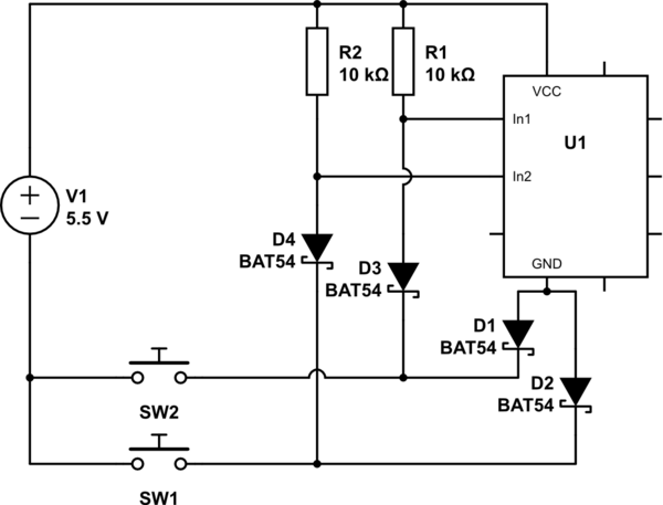
Okay, we found that is more or less working circuit, now another question:
How this would change if I power Arduino through it's RAW pin, using 12v battery? Do I still need to protect input pins using diodes and resistors or it's not necessary since internal voltage will always be the same 5v?
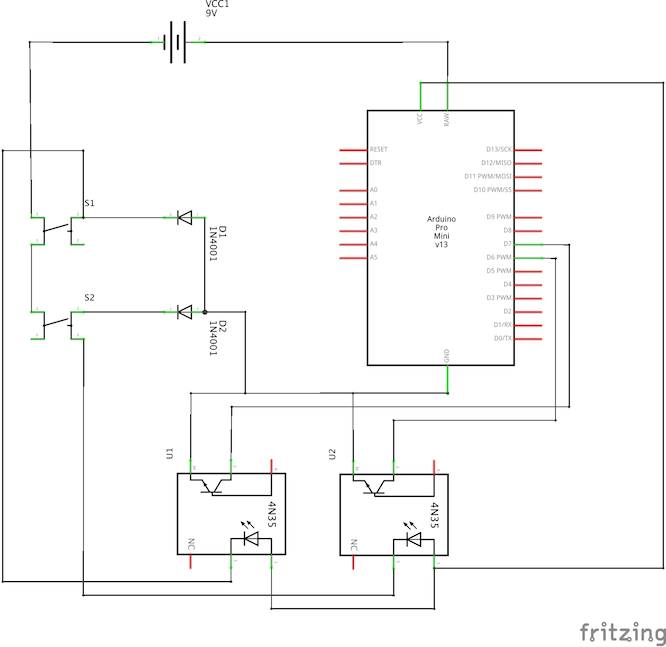
UDATE: I think I found another way of solving the problems with digital pin overvoltage:
Logic is pretty much the same, the only difference is that now digital inputs are pulled low using optocouplers, so the difference in the current between digital pin and the ground to which is connected - disappears, since it's the same ground as for Arduino.


