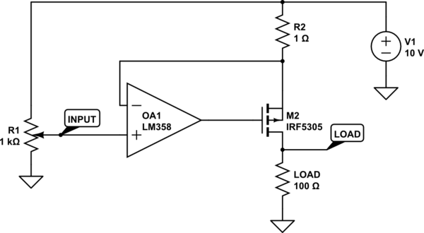
1
\$\begingroup\$

Why does this work?

schematic

simulate this circuit – Schematic created using CircuitLab

But this doesn't.
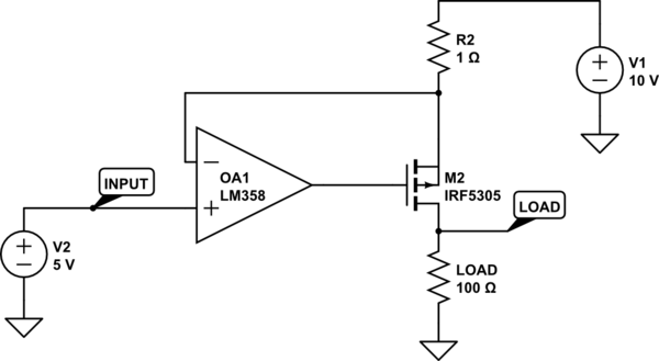
schematic

simulate this circuit

In the second schematic, V2 is adjustable.

Is there a better (not very complicated) way to make an adjustable current source where the LOAD is between Source (transistor) and GND (not with the sense resistor connected to GND and the LOAD on the high-side)?

Does the op-amp have to be powered with a dual power supply?

\$\endgroup\$
6
  • \$\begingroup\$ What current are you trying to get through the 100 ohm load? \$\endgroup\$ Commented Feb 16, 2016 at 8:34
  • 2
    \$\begingroup\$ Actually neither circuit works because the LM358 doesn't work properly with its inputs close to its positive rails. You should also have V2 referenced to the positive rail - it should not be ground referenced because THIS is not how this sort of current generator is intended to work. \$\endgroup\$
    – Andy aka
    Commented Feb 16, 2016 at 9:14
  • \$\begingroup\$ @SpehroPefhany I'd like to get a few amps if possible. The 100 Ohms is just a placeholder. LOAD will be from short (0 ohms) to whatever (until the voltage supply isn't able to provide the set current through the LOAD). \$\endgroup\$ Commented Feb 16, 2016 at 11:33
  • \$\begingroup\$ With your 1 Ohm current-sense resistor, the current will be set according to voltage on the (+) opamp input, where I = V1 - input. If the input = V1, the current will be zero. If the input is V1 - 1V (or 9V), the current will be 2A. Etc. This holds until the voltage across the load becomes so high that the FET cannot provide the current -- the Vgs needs to be a few volts for the FET to function (look at the FET specs). \$\endgroup\$
    – Paul
    Commented Feb 17, 2016 at 7:22
  • \$\begingroup\$ And then there's the opamp. It will probably not need dual supplies, but you need to be sure that the inputs can operate up to the V1 voltage. \$\endgroup\$
    – Paul
    Commented Feb 17, 2016 at 7:28

2 Answers 2

1
\$\begingroup\$

Start by assuming you have an ideal opamp. The second circuit is going to try to pull the non-inverting input down to +5V. This requires that 5A flows through the 1-Ohm R2 (a 10V supply, a 5V drop across R2). However, this same current would also have to flow through the 100 Ohm load, which is not possible with the 10V supply (5A * 100 Ohm = 500V).

The circuit would work if you replaced the +5V reference with one much closer to +10V.

\$\endgroup\$
1
  • \$\begingroup\$ So you're saying that in the first circuit, if I have the cursor of R1 at 500 ohms (resulting in 5V) it still wouldn't work? If that's so, than the adjustment would would need to be extremely fine, and I would need a multi turn pot. There has to be a better way. Took the schematic from The Art of Electronics, so maybe it does work but I'm missing something. \$\endgroup\$ Commented Feb 17, 2016 at 5:27
0
\$\begingroup\$

R2 is way way too low so the input of the opamp is right up near the rail .The workhorse LM358 is quite good with the inputs at or near the negative rail but it wont work with the inputs within less than a couple of VBE of the pos rail .The circuit as it stands is flawed and wont work .You could get a opamp that is specified to operate with its inputs at Vcc or you could run the opamp off a seperate higher voltage supply or you could just build the tried and trusted current sink with a N channel mosfet that has its pot going to ground and use a simple current mirror comprising 2 pnp BJTs to mirror to ground giving you the output that you want.

\$\endgroup\$

Your Answer

By clicking “Post Your Answer”, you agree to our terms of service and acknowledge you have read our privacy policy.

Not the answer you're looking for? Browse other questions tagged or ask your own question.