19
\$\begingroup\$

In mobile phones and other devices using a 3-axis electronic compass, a ∞/8/S shaped movement is used to calibrate the magnetometer as shown in these videos.

Why is this movement performed, what is the theory, and can anyone give some example C code to implement it?

You must have to go through my another similar question containing more info.


Some additional info for this particular question: The platform is 8-bit AtMega32, using AVR Studio 5.

Till now I've tried: I tried dividing the average by 2 of vector values of the Magnetometer making the shape. Thinking might help in calculating offsets. I think some how the two identical parts/sides of the shape is cancelling the earth's magnetic field and giving out the offset values. I might be wrong. But particularly for the shape based calibration this is where I am currently. I think the calibration works out this way. The idea is to find out does that work out this way?


Ok the code by which I can calculate the offsets and later simply subtract those from the Raw magnetic 3D vector. I might be totally wrong and have no explanation how it works. Seeing after the video and the data plotted on the sphere, somehow has accelerated my thought and I used that thought on form of equation. B)

Code:

The Read_accl(); and Read_magnato(1); functions are reading the sensor data. I hope the code is self explanatory. Hoping wise ppl will surely be using this in much better ways. :\

void InfinityShapedCallibration()
{
    unsigned char ProcessStarted = 0;
    unsigned long cnt = 0; 

    while (1)
    {

            Read_accl();

            // Keep reading Acc data
            // Detect Horizontal position
            // Detect Upside down position
            // Then detect the Horizontal position again.
            // Meanwhile an infinity shaped movement will be created.
            // Sum up all the data, divide by the count, divide by 2 .
            // !We've offsets.          

                if (ProcessStarted!=3)
                {
                //
                    //USART_Transmit_String("\r");
                    //rprintfFloat(4, g_structAccelerometerData.accx_RAW);
                    //USART_Transmit_String(",");
                    //rprintfFloat(4, g_structAccelerometerData.accy_RAW);
                    //USART_Transmit_String(",");
                    //rprintfFloat(4, g_structAccelerometerData.accz_RAW);

                }


            if (
             abs( g_structAccelerometerData.accx_RAW) < 100 
            && abs(g_structAccelerometerData.accy_RAW) < 100 
            && g_structAccelerometerData.accz_RAW < -350 
            && ProcessStarted != 2 && ProcessStarted != 3 && ProcessStarted != 1 )
            {
                ProcessStarted = 1; 
            }   

            if (ProcessStarted==1)
            { 

            Read_magnato(1);

                structMagnetometerOffsetDataToEEPROM.Off_X += g_structMegnetometerData.magx_RAW;
                structMagnetometerOffsetDataToEEPROM.Off_Y += g_structMegnetometerData.magy_RAW;
                structMagnetometerOffsetDataToEEPROM.Off_Z += g_structMegnetometerData.magz_RAW;

                cnt++;

            }               
                if ( g_structAccelerometerData.accz_RAW > 350 
                && ProcessStarted==1)
                {
                    ProcessStarted = 2; 
                }

                if ( g_structAccelerometerData.accz_RAW < -350 
                && ProcessStarted == 2 )
                {
                    ProcessStarted=3; 
                    structMagnetometerOffsetDataToEEPROM.Off_X /= cnt;
                    structMagnetometerOffsetDataToEEPROM.Off_X /= 2;

                    structMagnetometerOffsetDataToEEPROM.Off_Y /= cnt;
                    structMagnetometerOffsetDataToEEPROM.Off_Y /= 2;

                    structMagnetometerOffsetDataToEEPROM.Off_Z /= cnt;
                    structMagnetometerOffsetDataToEEPROM.Off_Z /= 2;  

                    UpdateOFFSETDATAinEEPROM();  

                    break;

                } 
    }   
} 

After getting these offsets I used them as follows:

void main()
{
...

Read_magnato(1);
        g_structMegnetometerData.magx_RAW -= structMagnetometerOffsetDataToEEPROM.Off_X ;
        g_structMegnetometerData.magy_RAW -= structMagnetometerOffsetDataToEEPROM.Off_Y ;
        g_structMegnetometerData.magz_RAW -= structMagnetometerOffsetDataToEEPROM.Off_Z ;
...
}

As I mentioned.

\$\endgroup\$
18
  • 2
    \$\begingroup\$ This question needs a lot of help. Do you need help with programming? Theory about magnetometers? What platform? What have you tried or looked up? \$\endgroup\$
    – Kellenjb
    Commented Nov 11, 2011 at 15:58
  • \$\begingroup\$ isnt the figure 8 simply a gesture to initiate calibration? \$\endgroup\$ Commented Nov 12, 2011 at 2:41
  • 1
    \$\begingroup\$ I don't know why ppl behave as if they are robot. I've given a link for the same work. I worked a lot on that and ppl just without knowing, just vote it down. I hate it when My question is down voted because of my unclear question. Please ask what needed just before voting it down. I really am dying to get outputs and ppl don't even think before voting it down. It feels bad and tries to divert me from working in the right direction. Please, I need help not either side of vote. \$\endgroup\$
    – Rick2047
    Commented Nov 14, 2011 at 7:05
  • 1
    \$\begingroup\$ @Kellenjb : I am working on an IMU using a simple 8-bit atmega32. I tried working on it and concluding that a 32bit uC is like using a sword in place of a needle. (Sorry for my riddle : )) I tried adding up all the RAW values of the Magnetometer making the shape. Then divide by the no of inputs. Thinking might help in calculating offset. I think some how the two identical parts/sides of the shape is some how cancelling the earth's magnetic field and giving out the offset values. I might be wrong. But particularly for the shape based calibration this is where I am currently. I think the ... \$\endgroup\$
    – Rick2047
    Commented Nov 14, 2011 at 7:17
  • 1
    \$\begingroup\$ The problem was not with the question, but with the number of people on this site who will downvote questions simply because they aren't familiar enough with the subject matter to understand what has been asked. If you don't know, just leave it alone! \$\endgroup\$ Commented Nov 15, 2011 at 4:56

1 Answer 1

26
\$\begingroup\$

The 8/S shaped pattern is used to calibrate magnetometers in mobile phones and other devices.

Background

Typical mobile phone era magnetometers measure the magnetic field strength along three orthogonal axes, e.g.:

\$\textbf{m} = m_x\boldsymbol{\hat{\imath}} + m_y\boldsymbol{\hat{\jmath}} + m_z\boldsymbol{\hat{k}}\$

With the magnitude of the field given by,

\$\|\textbf{m}\| = \sqrt{m_x^2 +m_y^2 + m_z^2}\$

and the angle of rotation from each axis as

\$ \theta_k = \cos^{-1} \frac{m_k}{ \| \textbf{m} \| }, \text{ where } k \in [x,y,z] \$

Calibration

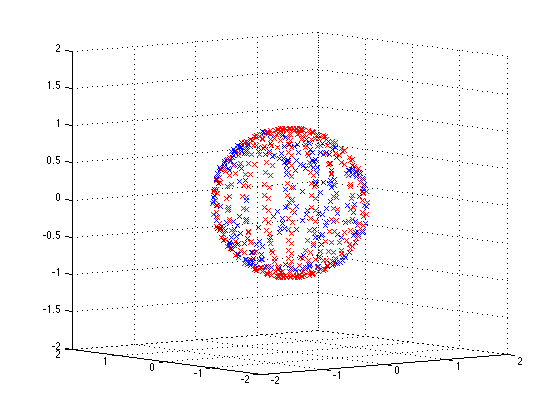
Since the magenetic field of the earth is relatively constant, the magnitude of the as field measured by the magnetometer should also be constant, regardless of the orientation of the sensor. i.e. if one were to rotate the sensor around and plot \$m_x\$, \$m_y\$, and \$m_z\$ in 3D, the paths should plot out the surface of a sphere with constant radius.

Ideally it should look somthing like this:

sphere

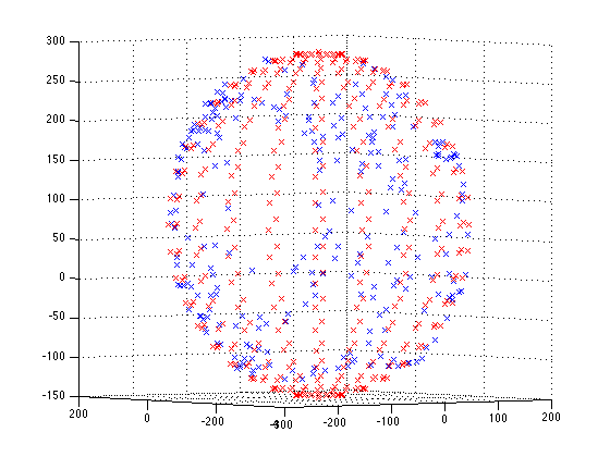
However due to hard and soft iron effects and other distortions, it ends up looking like a deformed sphere:

deformed

This is because the magnitude of the magnetic field as measured by the sensor is changing with orientation. The result being that the direction of the magnetic field when calculated according to the formulas above is different from the true direction.

Calibration must be performed to adjust each of the three axis readings so that the magnitude is constant regardless of orientation - you can think of it as the deformed sphere must be warped into a perfect sphere. The LSM303 application note has lots of detailed instructions on how to perform this.

So what about the figure 8 pattern!?

Performing the figure 8 pattern 'traces out' part of the deformed sphere above. From the coordinates obtained, the deformation of the sphere can be estimated, and the calibration coefficients obtained. A good pattern is one that traces through the greatest range of orientations and therefore estimates the greatest deviation from the true constant magnitude.

To estimate the shape of the deformed sphere, least squares ellipse fitting can be used. The LSM303 application note also has information on this.

A simple method for a basic calibration

According to the app note if you assume no soft-iron distortion, the deformed sphere will not be tilted. Therefore a simple method for a basic calibration may be possible:

  • Find the maximum and minimum value for each axis, and get the 1/2 range and zero point

\$r_k = \tfrac{1}{2} (\max(m_k) - \min(m_k))\$

\$z_k = \max(m_k) - r_k\$

  • Shift and scale each axis measurement

\$m_k' = \frac{m_k - z_k}{r_k}\$

  • Calculate values as before except using \$m_k'\$

This is based off the code found here.

Solving using least squares

MATLAB code to solve using least squares is shown below. The code assumes a variable mag where the columns are the x y z values.

H = [mag(:,1), mag(:,2), mag(:,3), - mag(:,2).^2, - mag(:,3).^2, ones(size(mag(:,1)))];
w = mag(:,1).^2;
X = (H'*H)\H'*w;
offX = X(1)/2;
offY = X(2)/(2*X(4));
offZ = X(3)/(2*X(5));
temp = X(6) + offX^2 + X(4)*offY^2 + X(5)*offZ^2;
scaleX = sqrt(temp);
scaleY = sqrt(temp / X(4));
scaleZ= sqrt(temp / X(5));

To do a dynamic figure 8 calibration, you could run the least squares routine with every new reading and terminate when the offset and scale factors have stabilised.

Earth's Magnetic Field

Note, the Earth's magnetic field is usually not parallel to the surface and there may be a large down component.

\$\endgroup\$
8
  • \$\begingroup\$ Hi,That's an appreciable effort you've made to clear the way for figure 8 pattern issue.Now I can connect some of my earlier work with current work.I did see some improvements but not upto the mark.As I explained earlier in this question only;the NEWS is shown correctly using the output data after making the 8 shape,then getting half of the average of all the vectors.Surprisingly it works for the horizontal plan(by fluke).So again I am at the same place from where I started working on the 8 shape algo.I'll b back after "Least Square".I am however not able to understand the fluke. \$\endgroup\$
    – Rick2047
    Commented Nov 15, 2011 at 6:36
  • \$\begingroup\$ ... Seems in my case also the sphere is deformed on Z axis. Please know that I am aware of Hard and Soft Iron effect on the plotted 3D sphere. I'll try to plot it on the 3D again. Let see. \$\endgroup\$
    – Rick2047
    Commented Nov 15, 2011 at 6:38
  • \$\begingroup\$ @Rahul2047 Well I just hope it is correct, but it makes sense to me. I have to do a similar calibration for an instrument I'm building but I'm not quite up to implementing the code yet. \$\endgroup\$ Commented Nov 15, 2011 at 7:58
  • \$\begingroup\$ I wonder that for phones which usually are only interested in direction in the horizontal plane, a simple gesture covers all the needed points. Do you use matlab? It is easy to do the fit in there. Least squares refers to the error measurement method. \$\endgroup\$ Commented Nov 15, 2011 at 8:09
  • 1
    \$\begingroup\$ Some of the image links in this article broke - can you re-add the images? SE now has a function that uploads the images and stores them locally, to prevent against future breakage. Thanks! \$\endgroup\$ Commented Dec 19, 2013 at 0:24

Your Answer

By clicking “Post Your Answer”, you agree to our terms of service and acknowledge you have read our privacy policy.

Not the answer you're looking for? Browse other questions tagged or ask your own question.