0
\$\begingroup\$

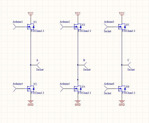
The attached Schematic uses 6 N Channel Power Mosfets "IRL3303". I have wound my inrunner bldc motor with 180 windings per phase using a 26 Gauge Magnetic Wire. My motor is a 6 pole 2 magnets machine. The encountered problem is defined below.

3 Phase Current Driver Schematic

Q. The mosfet being used has a Vgs Threshold as 1V. Arduino outputs are being used to power the mosfets(state-machine). Even at 15V VCC the drawn current by the motor is around 0.6AMPS. I have checked the winding connections seperately and it draws 2Amps at around 3-4V. My resistance per phase is around 5ohm and inductance 1.5mH. I have no clue how to fix it. Your input would be really appreciated. Thanks

\$\endgroup\$
2
  • \$\begingroup\$ "Even at 15V VCC the drawn current by the motor is around 0.6AMPS. I have checked the winding connections seperately and it draws 2Amps at around 3-4V", now what?? Does it draw 0.6A at 15V or 2A at 4V? You didn't mention the speed of motor, and if your state machine follows the rotor position - do you have any feedback like hall sensor or back EMF to give you the switch position? \$\endgroup\$ Commented Mar 26, 2016 at 8:12
  • 2
    \$\begingroup\$ What do your high side drivers look like? You can't just connect the upper FETs to Arduino pins. \$\endgroup\$
    – user16324
    Commented Mar 26, 2016 at 12:13

1 Answer 1

3
\$\begingroup\$

You are most likely not driving the high-side MOSFET with enough voltage to turn it on. You need to have VCC+1V or more at the gate to turn those on fully. Typically you would use a gate-driver IC to do this, which has a built-in boost circuit (bootstrap circuit).

\$\endgroup\$

Your Answer

By clicking “Post Your Answer”, you agree to our terms of service and acknowledge you have read our privacy policy.

Not the answer you're looking for? Browse other questions tagged or ask your own question.