0
\$\begingroup\$

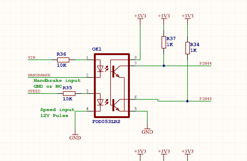
I have a opto coupler to detect 12v and use this on a micro controller at 3.3v Used the 4N25 before and they worked fine but i switched to the FOD053LR2 wich has 2 opto inside for better space usage.

i am not sure how to calculate the right resistors since the CTR is nog clear to me from the datasheet.

Below the schematic.

enter image description here

it also seems to me that PIN 3 and 4 are switched in the schematic and datasheet?

input voltage VIN is 12v ~ 18v

PDF of the opto coupler: http://www.mouser.com/ds/2/149/FOD053L-190687.pdf

\$\endgroup\$
1
  • \$\begingroup\$ According to the datasheet, the cathode of the lower LED should be on pin 3, not pin 4. \$\endgroup\$ Commented Mar 28, 2016 at 16:25

2 Answers 2

1
\$\begingroup\$

Dual optocouplers often have the second pair of inputs reserved. This is also the case for the FOD053L; the symbol is wrong, you have to exchange pins 3 and 4 in the schematic.

There is no single CTR value because the actual CTR varies greatly due to manufacturing tolerances. (And temperature, and forward current.)

To compute the required resistors for the input LEDs, go backwards from the outputs: with the 1K pullup resistors, the outputs need to sink about 3.3 mA. With the worst-case CTR of 15 %, the LEDs need a current of about 3.3mA/15% = 22 mA. With a worst-case voltage drop of 1.7 V over the LED, the input resistor needs to drop 12V-1.7V = 10.3 V, so at a current of about 22 mA, the resistor must not be larger than about 10.3V/22mA = 468 Ω.

Please note that 22 mA is dangerously near the absolute maximum, and this maximum is likely to be exceeded with a higher input voltage. You should consider increasing the pullup resistors; e.g., doubling them results in half the required LED current. (Increasing the pullup resistor makes the output switch off slower, as shown in figure 10 of the FOD053L datasheet. However, this is probably not a problem in your case.)

The FOD053L has a lousy CTR because it is a high-speed optocoupler. If your signals aren't faster than about 10 kHz, consider using a plain phototransistor optocoupler in a small package, such as the PC3H7 or one of its clones (Fairchild's is the HMHA2801).

\$\endgroup\$
0
\$\begingroup\$

1) You are correct - the schematic is wrong. Pins 3 and 4 are reversed.

2) Page 4 of the data sheet lists the CTR as 15 to 50%.

3) and yes, you should redo your resistors. At the very least, something like 1k on the LEDs is a good idea.

\$\endgroup\$
5
  • \$\begingroup\$ Thank you for the comment. How do i know wich CTR to use to calculate the correct resistor. \$\endgroup\$ Commented Mar 28, 2016 at 16:31
  • 1
    \$\begingroup\$ I always use the minimum CTR for my conditions if I want guaranteed operation. \$\endgroup\$ Commented Mar 28, 2016 at 16:36
  • \$\begingroup\$ I don't know why i got to 10k at first but i see know that it must be low about 680 but 1K would work to. \$\endgroup\$ Commented Mar 28, 2016 at 17:20
  • \$\begingroup\$ What would be a good value for the pullup resistor? \$\endgroup\$ Commented Mar 28, 2016 at 17:20
  • \$\begingroup\$ What do you think it would be, and why? Include your calculations. \$\endgroup\$ Commented Mar 28, 2016 at 17:24

Your Answer

By clicking “Post Your Answer”, you agree to our terms of service and acknowledge you have read our privacy policy.

Not the answer you're looking for? Browse other questions tagged or ask your own question.