2
\$\begingroup\$

I've got a circuit that looks like this:

circuit http://img.skitch.com/20111127-m6jqyx9b15brese4rkipayyib6.png

My input is low voltage AC at low current and I want to measure this with an ADC at 3.3V (eventually, haven't got there yet).

Is this safe/correct? It appears to do what I want when I measure it with my oscilloscope, but it feels strange to me to be sharing an AC line with my DC circuitry (both connect to the same 0V).

I'm having trouble preventing the signal from dropping below 0V. The closest I've got was to connect a schottky with the cathode to signal and the anode to ground. I'm still seeing 300-400mV below zero on the signal line at particular instants. I'm wondering if these things are related.

Edit: Expanding a bit with more data (and updated the circuit to show opamp power).

While most measurements seem to be doing the right thing, the bigger the burst, the more likely it seems that I'd damage the device offering the reference power (in the deployment, it will be an atmega running at 3.3V). I see drops down around -80mV or so, but when I had this hooked up to my washing machine, this happened:
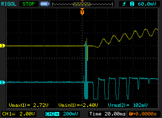
washer start

It leveled out pretty quickly, but my understanding of operational amplifiers is only slightly greater than my understanding of Aramaic. I've heard when you use them right, stuff like this doesn't happen. I do believe that -2.4VDC would be a Bad Thing to hand off to an ADC.

Is this the wrong way to do things?

\$\endgroup\$
8
  • \$\begingroup\$ The first issue I see is that your input (pin 2 of the connector) is effectively shorted to ground. Will the source be happy if its output is shorted? \$\endgroup\$
    – The Photon
    Commented Nov 27, 2011 at 2:03
  • 1
    \$\begingroup\$ Another possible issue is that the gain seems fairly high. If the source produces 1 mA when shorted, your circuit will try to produce a 50 V signal at the "signal" node. It would help to know more about the source --- what do you mean by "low voltage" and "low current"? Are we talking milliamps or nanoamps here? \$\endgroup\$
    – The Photon
    Commented Nov 27, 2011 at 2:05
  • \$\begingroup\$ I'm getting meaningful looking measurements with it (voltage goes up proportional to input). I got the circuit from this site. I don't fully understand it, so I just apply things I find and measure. I'm getting payback for all the programmers I've shaken my head at over the years. \$\endgroup\$
    – Dustin
    Commented Nov 27, 2011 at 2:08
  • \$\begingroup\$ Another possible issue is that you've got a low-pass filter with a cut-off frequency of 0.03 Hz. If your "AC" signal is actually slower than that, most of us wouldn't call it "AC" at all -- we'd just call it a varying DC value. So what is the frequency of your AC signal? \$\endgroup\$
    – The Photon
    Commented Nov 27, 2011 at 2:09
  • \$\begingroup\$ To be honest, I don't know how to measure the current. The specs on the device are pretty poor and I don't have a current meter. I can tell you the highest voltage I've measured off of it was around -48mV - 160mV (possibly lower, I got cut off). \$\endgroup\$
    – Dustin
    Commented Nov 27, 2011 at 2:12

2 Answers 2

3
\$\begingroup\$

Moving over to this question as it's related to my answer on your last one:

I checked to see if I could find some info on the CT and I discovered from the datasheet that that model is a voltage output version with a max output of 1V at 30A (assuming pk-pk AC), which means a transimpedance (current to voltage) amplifier is not what you want.
What you want is a simple buffer/level shifter.

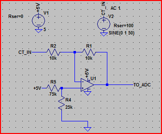
Something like this would do:

CT Buffer

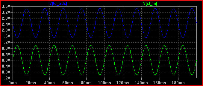
Waveforms:

CT Buffer Sim

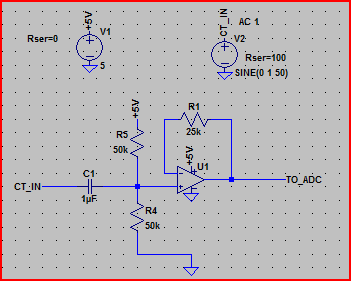
If you don't want an inverting buffer then you could try this kind of thing:

CT Buffer non inverting

If you want to match the range of the ADC then you can add some gain to either. Careful with the inverting version as the DC bias will be amplified. For a gain of 2.5 a ratio of 6 for R5/R4 is needed. Something like R1 = 25k, R5 = 60k, R4 = 10k should be okay.
Note that you need to make sure your opamp is capable of a rail to rail output swing if you want to use the full supply range (an example part from memory is the MCP6021, this does have R2R in/out IIRC)

\$\endgroup\$
1
  • \$\begingroup\$ I don't think I got good results out of the second one, but my results from your first circuit matched your readings approximately. I think the answer to my initial question seems to be "No." While playing with this circuit simulator, it seems that I can get quite near exactly what I want in the end results with a peak detection configuration. \$\endgroup\$
    – Dustin
    Commented Nov 28, 2011 at 2:26
1
\$\begingroup\$

One thing I'd add to Oli's answer is, if you just want to monitor the power drawn by some loads on your mains circuit, like the guy with the website was doing, you might not want to see all of the details of each cycle of the 60 Hz power line signal.

You could use the ADC to take a bunch of samples of the waveform, then do some signal processing to work out the RMS value, or you could add a little bit more to your analog circuit to pre-filter the signal. On the website you cited, he was using a meter device instead of just a simple transformer, and something like this was probably going on inside there.

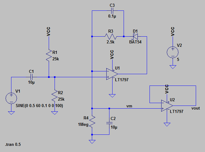
My first cut at this is something like this: peak detector circuit

But this does have a potential problems in that any spike coming from the sensor (like you asked about in another question) will show up as a disturbance in the output of this circuit, with a fairly slow decay rate.

I'm also sure there's lots of other improvements to be made if someone spent some more time working out the details of this circuit.

\$\endgroup\$
3
  • \$\begingroup\$ I don't understand the purpose of the opamp on the right. I just tried this in a circuit simuilator and didn't see much of a difference from the + input of the second opamp and its output. \$\endgroup\$
    – Dustin
    Commented Nov 28, 2011 at 1:14
  • \$\begingroup\$ The opamp at U2 is a voltage follower. It's there so that the load on vout won't change the behavior of the circuit. Without that buffer, any load less than about 10 MegOhms would change the behavior. \$\endgroup\$
    – The Photon
    Commented Nov 28, 2011 at 2:49
  • \$\begingroup\$ I should add, the LT1797 is probably not the ideal opamp there...it's input current is actually enough to change the time constant of the R4-C2 filter...a FET-input part would be better...this is just what I threw together quickly. \$\endgroup\$
    – The Photon
    Commented Nov 28, 2011 at 2:57

Your Answer

By clicking “Post Your Answer”, you agree to our terms of service and acknowledge you have read our privacy policy.

Not the answer you're looking for? Browse other questions tagged or ask your own question.