3
\$\begingroup\$

Let's assume we have a test set-up involving an oscilloscope and a unit we are testing. we measure the voltage between two points using a standard scope lead and see significant noise, I now take out a clip on ferrite wrap 2 or 3 turns around this ferrite and close it. The noise on my scope is visably reduced. What have I done?

We should note here that the scope is plugged into the wall and so connected to mains earth. The scope return lead is tied to earth via the scope and the UUT may otherwise be floating or tied to earth by a different route locally (same building).

My personal understanding is I have effectively added a common-mode choke in series with the signal and so I am filtering out at least some of the common-mode noise.

There is at least one user on this site who has a different opinion on this.

The last thing I want to do is start a flame war but I am sure in this case that we are both able to discuss this calmly and both keen to learn if we have misinterpreted things.

So does wrapping a scope lead around a ferrite reduce noise because it cuts down common-mode noise or some other method?

\$\endgroup\$
8
  • \$\begingroup\$ quora.com/… \$\endgroup\$
    – jonk
    Commented Oct 25, 2017 at 19:58
  • \$\begingroup\$ @jonk at the risk of starting an argument. That's a common mode choke, not really the same thing as few turns of a scope wire in a ferrite ring since in the latter the coils are in the same direction. That is. no cancellation effect. \$\endgroup\$
    – Trevor_G
    Commented Oct 25, 2017 at 20:18
  • \$\begingroup\$ Right that would be my understanding. I've never done this with a 'scope probe, but have used it for interconnecting cables, like usb. \$\endgroup\$ Commented Oct 25, 2017 at 20:32
  • 1
    \$\begingroup\$ @Trevor You've addressed what I wanted addressed in your answer. So there's no argument here. And in any case, I'm just a hobbyist sitting back watching and learning from all the excellent experts here. \$\endgroup\$
    – jonk
    Commented Oct 25, 2017 at 21:04
  • 2
    \$\begingroup\$ Sorry, I don't understand looi \$\endgroup\$
    – Trevor_G
    Commented Oct 25, 2017 at 21:29

3 Answers 3

1
\$\begingroup\$

What you are describing is a current balun which serves to add common mode impedance and thus limit the high frequency ground loop sometimes formed by longitudinal mode current flowing in the screen of the scope lead.

I have a couple made up on ETD cores wound with micro coax, occasionally very handy.

\$\endgroup\$
7
\$\begingroup\$

What you have added is a suppressor not a common mode choke.

By wrapping the cable around a ferrite core or bead you have added lossy inductors to the circuit. This does two things. The inductors limit high frequency transmission and the magnetics cross couples non-common noise.

A common mode choke is a different animal.

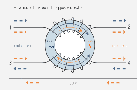
enter image description here

In a common mode choke the two wires are wrapped in different directions. Here the induced magnetism from the normal differential current and return current cancel out while the noise currents passing in both wires in the same direction, e.g. from left to right in the image above, double the magnetic effect. The signal therefore sees virtually no inductance and is not affected much while the noise sees lots of inductance and is "choked".

Correction:

After several hours of reflection it seems I may have been getting confused with my coil rules and directions.

A two core cable wrapped a few times through a toroid will indeed form the cancelling mode of a common mode choke, though perhaps not as efficiently as a classic purpose built model.

Which kind of makes sense since the current paths cancel each other in each cable core for differential signals while common mode noise sees basically one core split in two. Apologies.

Odd the original got 7 votes before I noticed... I guess it's confusing to more than just me.. all this left hand right hand rules round a torroid thing is hard :)

\$\endgroup\$
1
  • \$\begingroup\$ Looks wrong to me. If the differential current is the blue one and the common mode is orange then both windings should be in the same direction to cause the flux from the two orange currents to sum in the core. \$\endgroup\$
    – Dan Mills
    Commented Oct 25, 2017 at 22:34
1
\$\begingroup\$

Several turns of coax on a ferrite core is a COMMON MODE CHOKE.It is very effective in breaking up ground looks in any equipment (which is most probably not grounded well internally). It is a 1 to 1 transformer. Noise voltage developed across a coax shield (because of ground noise) is transformed to the inner signal line, allowing the coax ends to be at different potentials with respect to reference ground. Typical inductance of 3 T on a Fair-Rite products clip on core is about 20 uH. This is also a high freq bead material and helps damp HF noise out too. In the 1 MHz region it operates well as a transformer core. Mostly you are dealing with switching converter common mode noise generated by capacitive coupling throgh the converter transformer and ringing of the rectifier diodes. All problems for the switcher user, NOT FILTERED well by the switcher output filter.

\$\endgroup\$

Your Answer

By clicking “Post Your Answer”, you agree to our terms of service and acknowledge you have read our privacy policy.

Not the answer you're looking for? Browse other questions tagged or ask your own question.