1
\$\begingroup\$

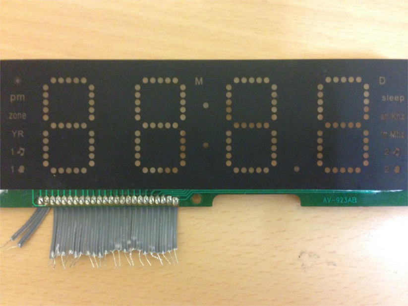
I have a display from an old radio (I think it was a Watson).

Picture of the display

Now, there are different wires connected to it: Let's call the first two A and B and one of the others (it seems to be not so important which you choose) C.

If I connect A to the (+) of a power source and C to the (-), LED M lights up. If I connect B to the (+) of a power source and C to the (-), LED N lights up. Using that technique, I can light up any LED on the display. (Connecting A or B to (-) and C to (+) yields no results). Also note that the display does not need a binary encoding (i.e., voltages LLHL -> number 2 on display); I am able to light up an arbitrary segment.

However, I can only light up one arbitrary LED; If I wanted to choose two arbitrary LEDs, I would have to connect for example A and B to (+) and the other wires C and D to (-). As one might expect, four LEDs light up, as a current flows from C to A but also from C to B and from D to B and also from D to A. Therefore, four LEDs light up.

Does anybody have an idea about how to control this type of display correctly?

There are also some notes on the back: AV-923A8Y, SB 98 IHB, E228731. However, I did not find any suitable (and free) data sheet.

\$\endgroup\$

2 Answers 2

3
\$\begingroup\$

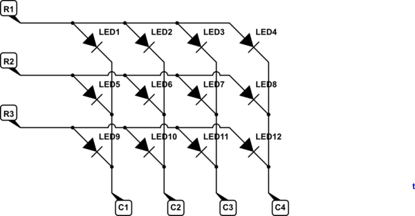
schematic

simulate this circuit – Schematic created using CircuitLab

Figure 1. Matrix display.

I think you are describing an LED matrix display. Each LED or "segment" of LEDs is on the intersection of a row and column which appear at your wires. Typically the controllers work by pulling each row high in turn while pulling the required columns low to turn on the LED at the intersection. The scan rate is set high enough so that the eye won't detect any flicker. LEDs can be run at higher current than their continuous rating since they are only on part of the time.

\$\endgroup\$
5
  • 1
    \$\begingroup\$ I've read about something similar. If I understand it correctly, the LEDs are turned on and off, in sequence, really fast, for it to seem to have multiple segments on while it only has a single segment on at a time. Kinda like persistence of vision? \$\endgroup\$ Commented Apr 14, 2016 at 1:12
  • 1
    \$\begingroup\$ Correct. Usually each segment is one LED. I can't tell from the OP's photo whether that one has one LED per dot or one LED per segment. You could have all the LEDs for a particular address row on at the same time, don't forget. Sometimes you can see a strobing if you roll your eyes or wave the display in front of your eyes while keeping them straight. \$\endgroup\$
    – Transistor
    Commented Apr 14, 2016 at 6:25
  • \$\begingroup\$ Oh, yeah. I notice the strobbing effect a lot on alarm clocks, which seems to be where the display came from. But can LEDs blink that fast without dying/frying or overheating or anything? \$\endgroup\$ Commented Apr 14, 2016 at 8:19
  • \$\begingroup\$ LEDs are solid state and don't exhibit surge current when cold in the way that incandescent lamps do. You can switch them as fast as you like. As with all LEDs, correct current control is vital to their survival. \$\endgroup\$
    – Transistor
    Commented Apr 14, 2016 at 17:45
  • \$\begingroup\$ That is something I wasn't aware of. Thank you for teaching me. \$\endgroup\$ Commented Apr 14, 2016 at 19:05
2
\$\begingroup\$

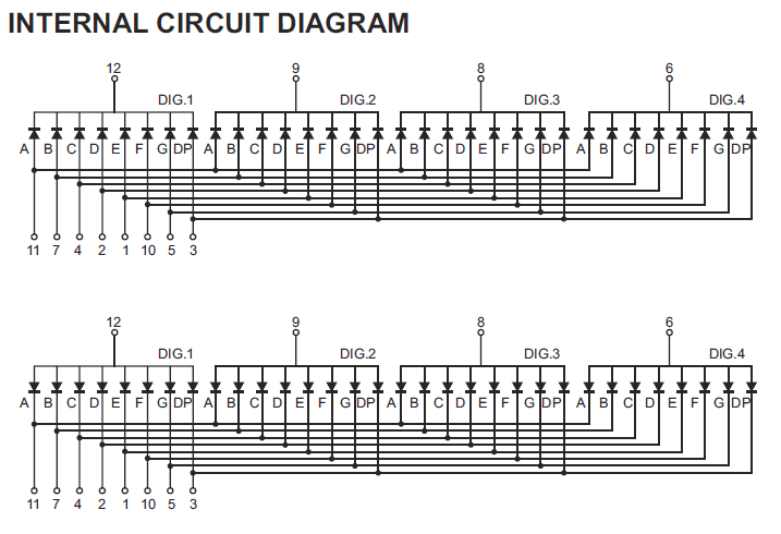
It's called multiplexing. Usually the internal schematic looks something like this (top is common cathode, bottom is common anode):

enter image description here

Using the bottom schematic you would drive pin 12 high, and any combination of 11,7,4,2,1,10,5,3 low through 8 individual resistors. That creates one character Dig 1 with the proper segments lit. If you only want one digit, you are done, but assuming that's not sufficient, what you do is

  1. Turn off drive to 12 (low or open)
  2. Real quick like set the 11,7,4,2,1,10,5,3 pins (through the same 8 resistors) low for each segment you want on for DIG 2. The others can be high or open.
  3. Drive pin 9 (DIG 2) high.

and repeat for DIG 3 and DIG 4

If you do that fast enough (a few hundred Hz) you achieve the appearance of any combination of segments being lit, but only a maximum of 8 are lit at one time. The apparent brightness is less since even the lit segments are off 75% of the time, but you can drive more peak current to compensate (within limits, obviously).

\$\endgroup\$

Your Answer

By clicking “Post Your Answer”, you agree to our terms of service and acknowledge you have read our privacy policy.

Not the answer you're looking for? Browse other questions tagged or ask your own question.