0
\$\begingroup\$

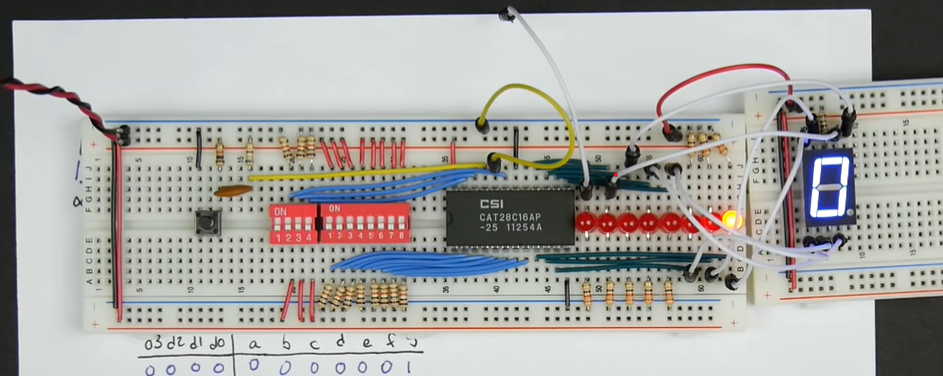
First question in this community, and I'm a beginner when it comes to circuits. In Ben Eater's video on using an EEPROM for combinational logic, he uses the output of an EEPROM to drive a common anode seven-segment display. It doesn't really seem like it should work the way it does, however.

Here's the setup in question (at the correct timestamp): https://youtu.be/BA12Z7gQ4P0?t=1309

enter image description here

The way I understand common anode to work is that a given segment of the display will only light up if it has a path to ground. In this setup, it looks like every segment has a path to ground from the white wires, through the LEDs, and to the resistors. But when the EEPROM is outputting high on a given bit, somehow the path to ground for that segment is blocked. Isn't there still a path to ground for that segment, though?

Update

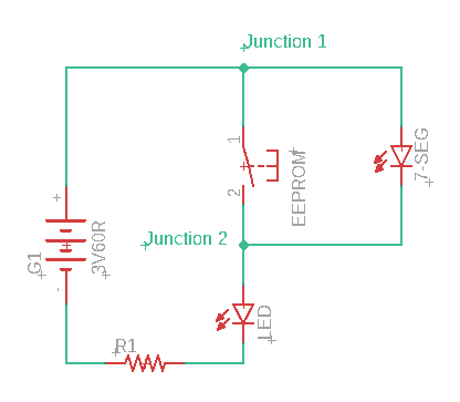
Would this be a correct representation of the circuit? The EEPROM essentially acts like a switch, so if it's open, all current travels through the segment of the LED. If it's closed, then the voltage at both junctions of the segment circuit are at the same voltage, so no current flows through that segment. That would make sense.

enter image description here

\$\endgroup\$
4
  • \$\begingroup\$ Since you are a beginner, it might be a good idea to reverse engineer his circuit. Draw a schematic , download and read the data sheets. \$\endgroup\$
    – Tyler
    Commented Aug 9, 2019 at 15:31
  • \$\begingroup\$ Can you share schematics of it.. wiring diagram of it. It will be easy to comprehend \$\endgroup\$
    – User323693
    Commented Aug 9, 2019 at 15:32
  • \$\begingroup\$ The EPROM is not a switch, it drives high or low. What is nasty about this circuit is that if you disconnect the EPROM, both the discrete LED and the digit segment may light, unless the sum of their forward voltages is so close to the supply voltage that miniscule current flows. In a dark room you might still see them lighting. That looks like it might be a white 7-seg so it may have a fairly high forward voltage. \$\endgroup\$ Commented Aug 9, 2019 at 16:28
  • 1
    \$\begingroup\$ Incidentally this demonstrates why video alone is a horrible medium - such a presentation needs to include static documentation which can be easily reviewed. If someone is going to be irresponsible enough to publish in video format only, the proper place for clarification questions is the comment section of their video. \$\endgroup\$ Commented Aug 9, 2019 at 16:32

2 Answers 2

0
\$\begingroup\$

Your mental model needs updating.

The way I understand common anode to work is that a given segment of the display will only light up if it has a path to ground.

An LED (by itself or inside a display) will only light up if it has current flowing through it. This will happen if it has voltage across it. One way of making this happen is to hold one end high and give the other a "path to ground" -- but that's not the only way, by any means.

In the common anode configuration, the anode is at VCC. When a cathode is pulled to ground through a resistor, current flows and the LED lights. When a cathode is "pulled" to VCC through a resistor, there is no voltage across the LED/resistor combination. No current flows, no light lights.

\$\endgroup\$
1
  • \$\begingroup\$ What you're saying definitely makes sense. I've updated my answer with a simple circuit diagram of one segment of the display. I think it's in line with what you're saying about the cathode being pulled to Vcc by the EEPROM, in which case I definitely understand it now. \$\endgroup\$
    – nmpauls
    Commented Aug 9, 2019 at 16:03
0
\$\begingroup\$

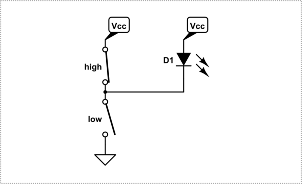
It's probably more like below. The output of the EEPROM isn't a single switch, but its driven either to Vcc or to ground (represented by the switches in the image). With the output high, the upper switch is closed, and there's no voltage difference over the LED, so no current. With the output low, the lower switch (only) is closed, and current flows through the LED. (There should be a current-limiting resistor too, and the switches would actually be FETs.)

schematic

simulate this circuit – Schematic created using CircuitLab

\$\endgroup\$

Your Answer

By clicking “Post Your Answer”, you agree to our terms of service and acknowledge you have read our privacy policy.

Not the answer you're looking for? Browse other questions tagged or ask your own question.