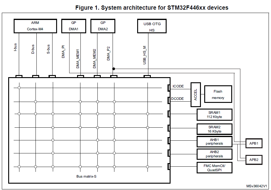
I'm using a stm32f446 and would like to use the TIM4_CH2 request with the DMA1 in Memory-to-peripheral mode to transfer data from an array to the ODR (output data register) of a GPIO port.
For some reason it only works with some destination addresses (and not with the &GPIOx->ODR address), even through the reference manual states at 9.3.6 Source, Destination and transfer modes:
Both source and destination transfers can address peripherals and memories in the entire 4 GB area, at addresses comprised between 0x0000 0000 and 0xFFFF FFFF
Is there any further restriction I should be aware off?
HAL_TIM_OC_Start(&htim4, TIM_CHANNEL_2);


uint16_t buffer[] = {1,2,3,4,5};
uint32_t dataLength = sizeof(buffer)/sizeof(buffer[0]);
uint32_t srcAddress = (uint32_t) buffer;
//uint32_t dstAddress = (uint32_t) &(TIM4->CCR2); // Works
//uint32_t dstAddress = (uint32_t) &(TIM4->CCR4); // Works
//uint32_t dstAddress = (uint32_t) &(TIM5->CCR4); // Doesn't work
uint32_t dstAddress = (uint32_t) &(GPIOC->ODR); // Doesn't work


HAL_DMA_Start_IT(&hdma_tim4_ch2, srcAddress, dstAddress, dataLength);
__HAL_TIM_ENABLE_DMA(&htim4, TIM_DMA_CC2);
The DMA initializing code:
hdma_tim4_ch2.Instance = DMA1_Stream3;
hdma_tim4_ch2.Init.Channel = DMA_CHANNEL_2;
hdma_tim4_ch2.Init.Direction = DMA_MEMORY_TO_PERIPH;
hdma_tim4_ch2.Init.PeriphInc = DMA_PINC_DISABLE;
hdma_tim4_ch2.Init.MemInc = DMA_MINC_ENABLE;
hdma_tim4_ch2.Init.PeriphDataAlignment = DMA_PDATAALIGN_HALFWORD;
hdma_tim4_ch2.Init.MemDataAlignment = DMA_MDATAALIGN_HALFWORD;
hdma_tim4_ch2.Init.Mode = DMA_NORMAL;
hdma_tim4_ch2.Init.Priority = DMA_PRIORITY_LOW;
hdma_tim4_ch2.Init.FIFOMode = DMA_FIFOMODE_DISABLE;
HAL_DMA_Init(&hdma_tim4_ch2);

__HAL_LINKDMA(htim_base,hdma[TIM_DMA_ID_CC2],hdma_tim4_ch2);
Timer configuration:
TIM_ClockConfigTypeDef sClockSourceConfig;
TIM_MasterConfigTypeDef sMasterConfig;
TIM_OC_InitTypeDef sConfigOC;

htim4.Instance = TIM4;
htim4.Init.Prescaler = 0;
htim4.Init.CounterMode = TIM_COUNTERMODE_UP;
htim4.Init.Period = 72;
htim4.Init.ClockDivision = TIM_CLOCKDIVISION_DIV1;
HAL_TIM_Base_Init(&htim4);

sClockSourceConfig.ClockSource = TIM_CLOCKSOURCE_INTERNAL;
HAL_TIM_ConfigClockSource(&htim4, &sClockSourceConfig);

HAL_TIM_OC_Init(&htim4);

sMasterConfig.MasterOutputTrigger = TIM_TRGO_OC2REF;
sMasterConfig.MasterSlaveMode = TIM_MASTERSLAVEMODE_DISABLE;
HAL_TIMEx_MasterConfigSynchronization(&htim4, &sMasterConfig);

sConfigOC.OCMode = TIM_OCMODE_TOGGLE;
sConfigOC.Pulse = 0;
sConfigOC.OCPolarity = TIM_OCPOLARITY_HIGH;
sConfigOC.OCFastMode = TIM_OCFAST_DISABLE;
HAL_TIM_OC_ConfigChannel(&htim4, &sConfigOC, TIM_CHANNEL_2);

