4
\$\begingroup\$

Usually I placed the 120 Ohm termination resistor pads in the PCB. So I could place the resistor or not during the PCB assembly for different applications.

However I suppose that the termination resistors should be a part of the transmission line - not the device. Besides, device user could be unaware of the fact that the termination resistor is already on the board and as the result - overload transducers.

On the other hand in case I don't have terminators on the PCB I will need them on the line which equals extra external components (terminal blocks, resistors...).

So the question is: which way will be the most convenient in terms of installation? Probably I could use 3-way RS485 terminal blocks (A, B, terminal resistor connected to the A or B). I could put a jumper accessible from the outside. Or finally I could skip the terminator at all as the speed id only 9600 baud (in my case).

Any thoughts?

\$\endgroup\$
1
  • 1
    \$\begingroup\$ Two microswitches? Is the most used way. The speed of transmission has no big importance for termination - this must exist on both ends. \$\endgroup\$ Commented Jun 4, 2016 at 16:21

3 Answers 3

4
\$\begingroup\$

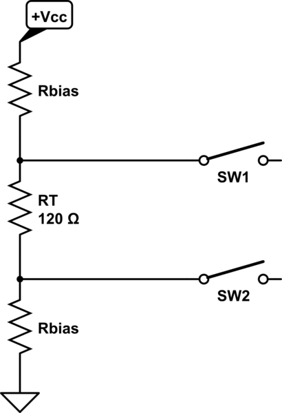
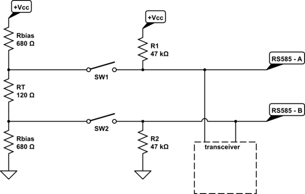
Use two switches, jumpers. Why two? Beacuse you need also to bias the signal.

schematic

schematic

simulate this circuit – Schematic created using CircuitLab

\$\endgroup\$
2
  • \$\begingroup\$ Is that correct that I need the biasing resistors at the EACH transducer? Or only on the ends (same as termination resistor)? \$\endgroup\$ Commented Jun 4, 2016 at 17:17
  • 1
    \$\begingroup\$ Rbias is somewhere 680ohm at both ends. In a isolated rs485 circuit then you will find usually also biasing resitors at each node, but those bias resistors are pretty high 47k and more, they help to define the potential of transceiver, as it is floating in case of isolated circuit. \$\endgroup\$ Commented Jun 5, 2016 at 8:31
2
\$\begingroup\$

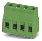
A common way to deal with the termination of RS485 busses is to deploy a connector similar to this one:

enter image description here

One scheme uses the four connections as:

  1. A
  2. TERM
  3. B
  4. GND

On the PCB behind the connector the termination resistor is mounted with one end connected to A or B signal. The other end connects to the TERM on the connector block. If the termination is required at this point a jumper is installed between TERM and the appropriate A or B connection.

Another thing sometimes done is to use a leaded 1/4 watt resistor and place it right into the A and B connection points along with the attached bus wires. Leave the resistor out of this connection point is not the end of the bus.

\$\endgroup\$
1
\$\begingroup\$

As long as your data rate is low (less than say 250 Kbits) you can use one of the slew rate limited devices and skip the terminations entirely. (You will save a little power by the way). All manufacturers make slew limited devices, but I'm most familiar with Maxim; look up the MAX483 for one of the oldest examples; there are many other choices

\$\endgroup\$

Your Answer

By clicking “Post Your Answer”, you agree to our terms of service and acknowledge you have read our privacy policy.

Not the answer you're looking for? Browse other questions tagged or ask your own question.