0
\$\begingroup\$

Could someone help me understanding the markings of this schematic? What the little numbers I circled in red and yellow areschematic.
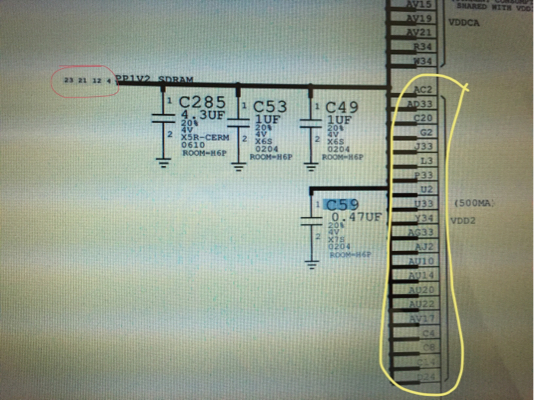
Is c59 providing power to that entire circled area or is just two points in between it? What about the other row of caps above it?

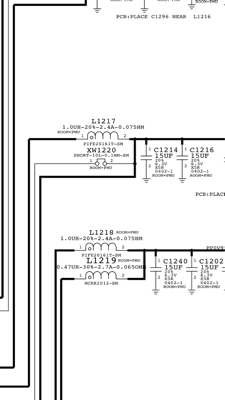
What about here with L1217 and XW1220 is that a jumper? And what does the dot on the (1) of L1217 mean? schematic2
\$\endgroup\$
3
  • 1
    \$\begingroup\$ You could take a screenshot instead of a photo of the screen :) \$\endgroup\$
    – David
    Commented Jul 22, 2016 at 22:27
  • \$\begingroup\$ Lol I don't have the schematic on my phone which is what I'm posting the question from \$\endgroup\$
    – ohmmy
    Commented Jul 22, 2016 at 22:28
  • 3
    \$\begingroup\$ Next time you want hundreds of people to read your question and help you, take 30 seconds of your precious time to copy the image to your cellphone unless you can't use a real computer to post a question. \$\endgroup\$
    – pipe
    Commented Jul 23, 2016 at 1:15

2 Answers 2

3
\$\begingroup\$

Could someone help me understanding the markings of this schematic? What the little numbers I circled in red and yellow are

  • The numbers you have circled in yellow, are the BGA ball numbers on that IC (cut off on the right side of the schematic photo you included).

  • The numbers you have circled in red, are the page numbers in this schematic diagram where that "net" (circuit connection) continues. On yours, it looks like pages 23, 21, 12 & 4 all have components connected to the PP1V2_SDRAM "net" (in this case, it's a supply voltage of some kind).

You already have an answer from Dave for the third part of your question, regarding C59.

\$\endgroup\$
2
  • \$\begingroup\$ @ohmmy - You're welcome - feel free to upvote answers that help, including Dave's too :-) \$\endgroup\$
    – SamGibson
    Commented Jul 22, 2016 at 23:15
  • \$\begingroup\$ Will do. Can you comment on my addition to the original post? \$\endgroup\$
    – ohmmy
    Commented Jul 23, 2016 at 0:56
2
\$\begingroup\$

C59 isn't "providing power" at all. It's merely functioning as a bypass capacitor (in parallel with C49, C53 and C285) between that 1.2V supply rail and ground. All of the pins that are connected by that heavy line are connected together electrically.

\$\endgroup\$
4
  • \$\begingroup\$ So if c59 were missing would it mean 1.2v doesn't reach that circuit or wouldn't affect it due to the other 3 caps? \$\endgroup\$
    – ohmmy
    Commented Jul 22, 2016 at 22:50
  • \$\begingroup\$ No, not at all. If C59 were missing, it would just mean that the power bus is a little noisier than it should be. Everything is connected in parallel, not in series. \$\endgroup\$
    – Dave Tweed
    Commented Jul 22, 2016 at 22:52
  • \$\begingroup\$ Yeah it just confused me that c59 wasn't just placed in the same line as the top 3 caps? But instead by itself below them \$\endgroup\$
    – ohmmy
    Commented Jul 22, 2016 at 22:56
  • \$\begingroup\$ Depending on how power is provided, without the cap things can go very wrong. An LDO might become unstable, or you can get a capless buck. Not nice. \$\endgroup\$ Commented Jul 22, 2016 at 22:57

Your Answer

By clicking “Post Your Answer”, you agree to our terms of service and acknowledge you have read our privacy policy.

Not the answer you're looking for? Browse other questions tagged or ask your own question.