3
\$\begingroup\$

I have some understanding of general electronics but now I want to learn about actual electronic schematics. For this I look at some complex reference designs to somehow get an understanding because like this I usually learn best.

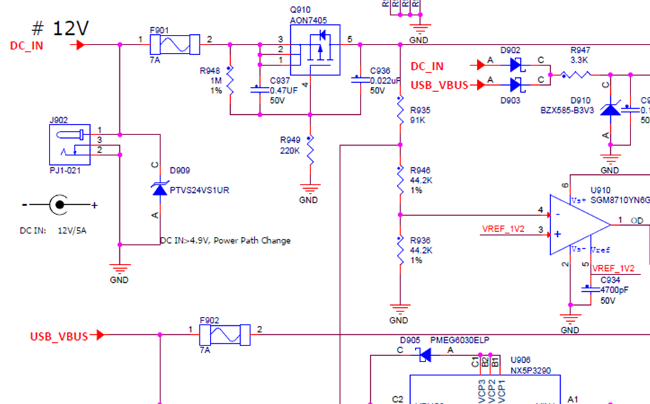
I came across this reference design where I cut out a part that I simply do not really understand. This shows the actual power/dc-connector input to the circuit.

However what I do not really understand are the voltage line arrows (like DC_IN). Since there is already the dc connector (PJ1-021) where pin 1 should be the voltage/power-in line why is there another red DC_IN arrow that points into the circuit (on the upper left)? I would understand if this arrow would point out of the schematic to show that it is used somewhere else. Is this arrow direction a mistake or am I understanding something completely wrong here?

And if this is not a mistake where does this 12V come from if not from the dc connector (PJ1-021)?

enter image description here

\$\endgroup\$
2
  • \$\begingroup\$ It comes from somewhere on your original diagram that you have conveniently not put into the snippet (just like USB_VBUS). Or, the originator is using the arrow symbol as something that names nodes. \$\endgroup\$
    – Andy aka
    Commented Oct 16, 2019 at 11:01
  • \$\begingroup\$ No there is no out-pointing dc_in arrow in the whole schematic. I used a search function to verify it. \$\endgroup\$ Commented Oct 16, 2019 at 11:08

1 Answer 1

3
\$\begingroup\$

You answered your own question here:

I would understand if this arrow would point out of the schematic to show that it is used somewhere else

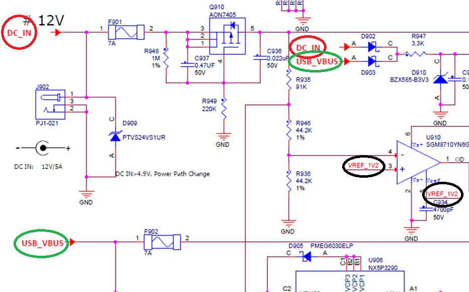
If you look at the schematic, you can see where it is also used in that snippet, along with some others too:

enter image description here

It is likely there is a backup 12V supply, or the arrow could mean nothing, and it is just there to name the net, so they don't have lines crossing all over the place. It depends who drew it.

Without the rest of the schematic, it is difficult to say for certain, but what we can say is this DC_IN net is used in other places of the schematic, so naming the net makes the drawing much easier to read.

\$\endgroup\$
2
  • \$\begingroup\$ Okay so to get my understanding right here: the arrow pointing direction does not really have a meaning here? It just says arrows with same name are directly connected? \$\endgroup\$ Commented Oct 16, 2019 at 11:11
  • \$\begingroup\$ @Marcel_marcel1991 That does depend on who is drawing the schematic. I tend to use different directional arrows for inputs and outputs, but I have also seen some where just 1 arrow type was used. Some just name the nets with no arrows too.... So I would not worry too much about that. Just focus on the net name and you'll be fine. \$\endgroup\$
    – MCG
    Commented Oct 16, 2019 at 14:23

Your Answer

By clicking “Post Your Answer”, you agree to our terms of service and acknowledge you have read our privacy policy.

Not the answer you're looking for? Browse other questions tagged or ask your own question.