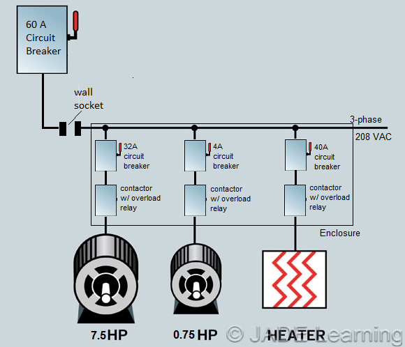
I'm connecting two electric motors and an electric heater in parallel together in a circuit, all three phase. Electric motor 1 has a rated current of 20A, motor 2 is rated 2.5A, and the heater is rated 25A. Branch circuit conductor sizing per the NEC is as follows: 125% of highest rated motor full load current (FLC) + 100% of each other motor FLC + 125% of non-motor noncontinuous load FLC. This totals to an FLC of about 59 amps. A conductor carrying 59A should be about 6 AWG THHM wire. My question is this, do I need to be running 6 gauge wire throughout my circuit (contactors, circuit breakers, etc)? This seems to be what the NEC recommends, but shouldn't the small motor receive 2.5A at most, why does it require such a thick wire?
-
\$\begingroup\$ Because (presumably) you have the branch circuit protected with a 210.20 Overcurrent Protection device rated at about 59 amps. \$\endgroup\$– TylerCommented Aug 8, 2016 at 19:27
-
\$\begingroup\$ Yes, the branch and motors have circuit breakers for overcurrent protection. \$\endgroup\$– schafboCommented Aug 8, 2016 at 19:37
-
\$\begingroup\$ Are the breakers in the industrial control panel rated for branch circuit protection, or are they supplementary protectors? \$\endgroup\$– ThreePhaseEelCommented Aug 9, 2016 at 0:20
-
\$\begingroup\$ I believe from NEC 430 you're required to have short circuit and ground fault protection for each motor. \$\endgroup\$– schafboCommented Aug 9, 2016 at 13:02
1 Answer
The wire gauge required by the NEC is determined by the circuit breaker protecting the branch. In the case of a short, even in a low current branch, the wire conductors need to be able to handle the momentary over-current of the short. If the short is not "perfect", the breaker will happily supply 60 Amps+ into it for an indefinite period of time. Not a good situation if the conductors are sized to carry 2.5 amps (presumably #14 wire, the smallest permissible gauge for branch circuits). For safety all branches of the circuit are assumed in the NEC regs to be able to carry the amperage dictated by the circuit breaker serving that branch.
By the way, if you have "long" cable runs to the high amperage motor you may find that the motor is starved for starting current due to the round-trip resistance of the conductors. This resistance may create a voltage drop in the wires sufficient to prevent the motor from starting, or cause it to start slowly or erratically. In your specific case you have that 25 Amp heater complicating matters. If the heater is also on the same long branch of the circuit, it will create its own voltage drop in the wiring which will affect the voltage available to the motor when it starts. In these cases you will need to use a heavier gauge cable than is dictated by the normal ratings of the motor.
-
\$\begingroup\$ If you used smaller gauge wire after the motor circuit breaker, wouldn't the breakers protect the conductor? Also, isn't the resistance in a 6 AWG cable fairly negligible? The round trip distance through the cable and branch circuit couldn't be more than 100 feet. I am not sure about the heater's resistance. \$\endgroup\$– schafboCommented Aug 9, 2016 at 13:06
-
\$\begingroup\$ schafbo: I wrote my answer just before you posted the wiring diagram. On the face of it you could easily use #14 AWG wire for the small motor branch between the 4 amp breaker box and the motor. However, as ThreePhaseEel suggests, the "legitimacy" of the branch circuit under NEC regs will depend on the nature of the circuit breaker.( I'm a bit out of my comfort zone in this area of the NEC regs.) Also, what's up with the "Wall Socket" in the diagram, that is not mentioned in the text? Is it there for additional devices, or does it actually connect the 60 Amp branch to the three devices shown? \$\endgroup\$– FiddyOhmCommented Aug 9, 2016 at 19:25
-
\$\begingroup\$ schafbo: Regarding #6 AWG copper wire, it has a resistance of approximately 0.4 milli-Ohms per foot. Or, 80 milli-Ohms for the 200 ft round trip. Insignificant? Probably. Do you know what the instantaneous starting current is for the "20 Amp" motor? In other words, how much current it will draw from the mains for the first cycle or two when voltage is applied with the rotor at a dead stop, and under its normal starting load. \$\endgroup\$– FiddyOhmCommented Aug 9, 2016 at 19:39
-
\$\begingroup\$ I think I've misunderstood the NEC regarding what a feeder and branch circuit is. I'm not an electrician, but I assumed a 'feeder circuit' was the connection into the master breaker from the electrical grid and a 'branch' was any wires beyond the master breaker. But now I see that a 'motor feeder' is the wire connecting multiple motors in parallel, I wasn't reading the diagram from NEC 430.1 correctly. The wall socket just shows that I'm connecting a control panel to the master circuit breaker, the enclosure just also happens to have circuit breakers in it. \$\endgroup\$– schafboCommented Aug 9, 2016 at 20:22
-
\$\begingroup\$ The inrush current for the large motor is 70A (I think in general it's about 4 times the rated current) but the circuit breakers are time delay so they shouldn't be tripping. \$\endgroup\$– schafboCommented Aug 9, 2016 at 20:30

