0
\$\begingroup\$

I have an electrocardiogram sensing circuit that uses an INA321 amplifier for common mode rejection on two measurement electrodes. The device is meant for hand-to-hand measurement of the heart rate and powered by a low voltage.

If supplied by batteries, the circuit works well. However, the device is now connected to a small computer and screen for demonstration purposes. The switiching power supplies of such devices tend to couple about one half of the mains voltage into the common ground of the devices. I guess they use two equally large capacitors between ground and the two mains supply lines for some unknown purpose. The INA321 can never reject 110V of course, in respect to the heart signal of about 1mV and having it powered with 3 to 5 volts.

Even if I connect the system ground to the mains protective earth, there is still a voltage up to 50V between mains protective earth and the body standing on the ground.

So is there any way to supply computer and screen without having them tied to some hefty earth capacitance?

\$\endgroup\$
7
  • 1
    \$\begingroup\$ Furthermore, the test subject can't reject 110V either. [Sorry, I couldn't resist.] \$\endgroup\$ Commented Aug 17, 2016 at 21:09
  • \$\begingroup\$ The test subject can easily pull down this 110V to some moderate level. It is not feelable in any way. The capacitance isn't just that large. I also checked some other devices device just for understanding.. for example laptops: Body to Thinkpad about 5V, body to Mac Book: 120V. Maybe it's time to start some fanboy war on electrically charged computers :-) \$\endgroup\$
    – dronus
    Commented Aug 17, 2016 at 21:14
  • \$\begingroup\$ If you only need to make a quick demonstration, then run the laptop from the battery. But I have a gut feeling that you may have errors in your EKG setup. Do you have a 2-electrode or a 3-electrode setup? When powered from a computer, do you pick up the power from USB jack? If you could post a schematic snippet of your front end, that would help. \$\endgroup\$ Commented Aug 17, 2016 at 21:19
  • \$\begingroup\$ It uses just two electrodes, and it is for public demonstration (eg. fairs), so there is no good possibility to add a third electrode to the leg or whatever. People just get the grip on two handles and that should be enough. \$\endgroup\$
    – dronus
    Commented Aug 17, 2016 at 21:32
  • \$\begingroup\$ If there is 50 AC Volts between the protective earth and the body standing on the ground then the bonding of the protective earth to an earth grounding rod DOES NOT EXIST. This is called a floating ground and because of capacitive coupling between HOT/GND and GND/NEUTRAL it will float some where less then 120VAC/2. \$\endgroup\$
    – Harvard
    Commented Aug 17, 2016 at 21:53

4 Answers 4

0
\$\begingroup\$

I would think about keeping the device powered as it is, and getting the data to the computer using an optically isolated link so that there is no galvanic contact between the two.

\$\endgroup\$
7
  • \$\begingroup\$ Sounds cool, I will try an opto-insulatior for the data connection. However, powering the device will be problematic, as batteries won't work that long. Would an old-school stabilized wall wart supply (with mains transformer) give a smaller capacitance as modern supplies? \$\endgroup\$
    – dronus
    Commented Aug 18, 2016 at 0:13
  • \$\begingroup\$ You mean trafo to bridge rectifier with caps, to linear voltage regulator(s)? It's hard to say how the sensitive device would perform on this power supply, but the experimental bar for trying it is quite low. Definitely, you're isolated from mains power, at least. \$\endgroup\$
    – Kaz
    Commented Aug 18, 2016 at 0:34
  • \$\begingroup\$ LiPo batteries should run along time. \$\endgroup\$
    – D.A.S.
    Commented Aug 18, 2016 at 0:37
  • \$\begingroup\$ I will look for an old wall wart and see. Modern wall warts provide quite strong capacitance to the live wires as can be seen... \$\endgroup\$
    – dronus
    Commented Aug 18, 2016 at 1:00
  • 3
    \$\begingroup\$ @dronus If you are foregoing battery power, you must look up the requirements for mains-connected power supplies in medical applications. \$\endgroup\$ Commented Aug 18, 2016 at 1:07
0
\$\begingroup\$

Even if I connect the system ground to the mains protective earth, there is still a voltage up to 50V between mains protective earth and the body standing on the ground.

Then your mains protective earth is floating and is not bonded to an Earth Ground Electrode as it should be. The 50 VAC is a result of the capacitive coupling between HOT/GND and GND/NEUTRAL where GND is allowed to float.

\$\endgroup\$
3
  • \$\begingroup\$ A symmetric coupling leads to about 110V, as I have mains voltage of >220V here. The 5-50V range is between my body and protective earth. It is not earth that is floating, but my body, as it is connected by shoes and concrete floor, both not very condictive, to the earth. I guess the body just picks up noise from the buildings environment, there is a plethora of electric devices around me. \$\endgroup\$
    – dronus
    Commented Aug 18, 2016 at 0:10
  • \$\begingroup\$ without a better CM coupling to ground, even thru one thumb, you won't be able to improve. \$\endgroup\$
    – D.A.S.
    Commented Aug 18, 2016 at 12:26
  • \$\begingroup\$ Well, with local decoupling (small battery powered device) there are large improvements over mains powered. The floating device has extraordinary small ground capacitance so the electrodes bias inside the amplifiers range and CM by the instrumentation amplifier is working. Which would never work with a CM offset of 110V of course. \$\endgroup\$
    – dronus
    Commented Aug 19, 2016 at 0:23
0
\$\begingroup\$

FLoating differential inputs connected to skin attached to electrodes have a certain isolation capacitance to line voltage which is easily detected.

The body is about a 300pF stray capacitor to E fields or ground depending on proximity without contact.

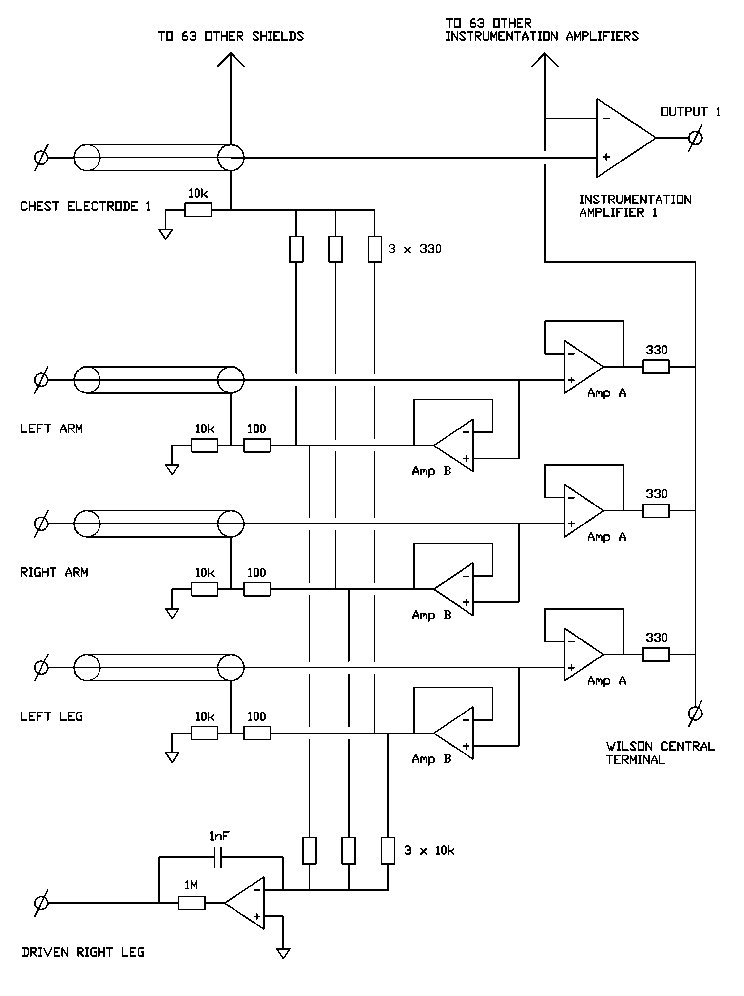
The Common Mode (CM) voltage must be suppressed either by connecting "right leg and the best practice is called "active" guard which drives the signal back on the return wire shield.

enter image description here

\$\endgroup\$
2
  • \$\begingroup\$ Driving the leg would require an additional electrode that can not be just gripped. While this may provide even better noise supression, the performance of two electrodes with the device isolated was by far good enough. I just need this performance with the device coupled to a computer. \$\endgroup\$
    – dronus
    Commented Aug 18, 2016 at 0:58
  • \$\begingroup\$ Then it will have be a battery powered computer \$\endgroup\$
    – D.A.S.
    Commented Aug 18, 2016 at 3:31
0
\$\begingroup\$

Consider using the INA149 opamp. It has a 2x 275V input voltage common mode range.
Great specifications. If you can live with 1mV offset and the 1/f noise

Apart from that, I don't like the driven right leg method to reduce the common mode voltage. There's a better solution. Greetings, Paul Keijzer Delft.

\$\endgroup\$
1
  • \$\begingroup\$ Hi! THe problem was solved already by optical insulation, see above. Better rejecting opamps may solve the problem, but may fail too, if common mode is higher (eg. static eletricity). \$\endgroup\$
    – dronus
    Commented Apr 30 at 13:59

Your Answer

By clicking “Post Your Answer”, you agree to our terms of service and acknowledge you have read our privacy policy.

Not the answer you're looking for? Browse other questions tagged or ask your own question.