The problem is that you selected a power supply that provides no working headroom for your LED. It's as though you just expected to get a power supply with the voltage rating of your LED. And that's not good, because now you are left with nothing much to work from. Let me explain my reasoning here:
Your LED is specified to operate at \$38V\$, while requiring \$2.1A\$. Your power supply is rated to supply \$36V\$, with a compliance of up to \$9.7A\$. On the compliance rating, your fine. But on the voltage specification, you are under-voltage, already. (And that's just using their typical rating -- the actual value may vary from there.) The datasheet for the LED does suggest that it may require \$760mA\$ when operating at \$36V\$. But devices vary and there is not even close to a guarantee of that. In fact, you will have widely varying currents (and therefore widely varying light outputs) from different devices running off that voltage.
It's just not a way to go.
You need some headroom voltage. You don't have any. So it is very hard to come up with a circuit that will regulate the current into your LEDs when you have no margin to work with.
Now, let's say you wanted to actually use a standard COTS power supply like the one you do have, but wanted to add a custom, but simple and cheap, current control circuit to it for your LEDs. (Let's say you want to really just use jelly-bean everything here.) How might you proceed?
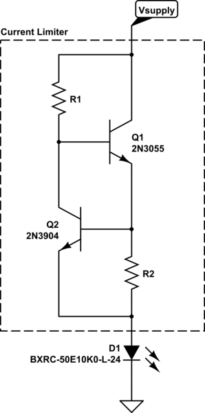
Well, you might start out with something like this:

simulate this circuit – Schematic created using CircuitLab
But now you need to figure things out from here.
\$Q_1\$ is your main pass transistor here. These are dirt cheap, available everywhere in the world, supplied by many, and available in various packages and similar names if you look around. They are ubiquitous and can handle the \$< 3A\$ need, easily. \$R_1\$ is there to turn \$Q_1\$ on and to supply its needed base current. We don't yet know the value for \$V_{supply}\$ so we can't specify the value of \$R_1\$ just yet. But we can say that you may require something on the order of \$\frac{2.1A}{\beta=20} \approx 105mA\$ in order to get \$Q_1\$ sourcing \$2.1A\$ for your LED.
\$Q_2\$ is there to measure the actual current flowing and to control \$Q_1\$, accordingly. The idea here isn't too complicated, either. \$R_2\$ is in the direct path from \$Q_1\$ to your LED. So nearly all of the current used by the LED must go through \$R_2\$ (except for some bypass current via \$Q_2\$ used to control \$Q_1\$.) That current causes a voltage drop across \$R_2\$. This voltage drop will be \$V_{drop_{R_2}} = I_{LED}\cdot R_2\$. \$R_2\$ here is arranged so this voltage drop is felt or observed by \$Q_2\$ as between its emitter and base. So, with a low voltage drop \$Q_2\$ will stay OFF. When \$Q_2\$ is off, then all of the current through \$R_1\$ will feed the base of \$Q_1\$, turning it hard-on and supplying lots of current through \$R_2\$ and into your LED. So, technically, we really don't want \$Q_2\$ to be OFF. We want it to be measuring current and siphoning away base current from \$Q_1\$ -- just enough to get things right. Roughly speaking, \$Q_2\$ will have a "turn on" voltage of about \$700mV\$ in normal (low current) operation. But we are talking here about hundreds of mA, not tens of mA. It's time to pause for a moment and discuss those currents now.
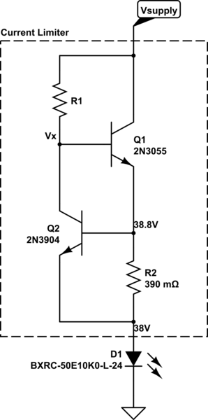
We know we will need about \$110mA\$ base drive for \$Q_1\$. But let's give it more than enough. Let's arrange for \$200mA\$ to drive \$Q_1\$ and plan on having \$Q_2\$ divert away whatever amount is in excess of the required amount. This means \$Q_2\$ will be expected to pull away about \$100mA\$. So we can expect \$V_{BE_{Q_2}} = 700mV + 60mV\cdot log10\left(\frac{100mA}{4mA}\right) \approx 800mV\$. So \$R_2 = \frac{800mV}{2.1A} \approx 0.38\Omega\$. Make that a standard \$0.39\Omega\$ resistor value. Power in it will be under \$2W\$, so pick out a \$5W\$ resistor for that. Now we have an estimated value for \$R_2\$.
Let's look at the schematic again:

simulate this circuit
We need to find the value of \$V_x\$ there. Or estimate a reasoned value for it. From the 2n3055 datasheet from OnSemi I see that at \$4A\$ collector current (not too far from where you want to be), the worst case is \$V_{BE} = 1.5V\$. It may be better than that, and probably will be. But we have to plan for the worst case. So let's set \$V_x = 38.8V + 1.5V = 40.3V\$.
Now, also from the datasheet I know that they specify a minimum \$\beta = 20\$ also when \$I_C=4A\$. I used that value above. So that's good. But also, that \$\beta=20\$ is for the case where \$V_{CE} = 4V\$. So we need to have a power supply rail that is \$V_{supply} \ge \left(38.8 + 4V = 42.8V\right)\$.
So now here we are. You can see why you need some headroom and that you need to get a power supply that is at least \$43V\$ or so. But you need to go search and see what you can find there.
Higher voltages will drop more volts across \$Q_1\$ and \$R_1\$ and heat them up. (We haven't even figured out what \$Q_2\$ will dissipate, yet.) So you don't want to just get some big iron here. Perhaps \$48V\$ might be a standard value you could find. But that's a bit high. Perhaps \$45V\$? I honestly don't know.
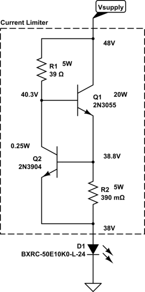
Let's say you are stuck getting a \$48V\$ supply. Here is the final circuit then:

simulate this circuit
The actual operating points will vary by the transistors you use. And that means the actual dissipation will vary some. The resistors are over-specified, though, so even if \$Q_1\$ doesn't need that high of a \$V_{BE}\$ (and it won't), \$R_1\$ will still be fine using \$5W\$. So it is safe to use \$5W\$ types. And the BJT dissipations are close enough that I don't think you'll go wrong with those estimates for power. The 2N3055 will definitely need a heat sink. I didn't find a thermal resistance on OnSemi's datasheet for junction-to-air. But I'd heat-sink the thing at \$20W\$ dissipation.
Note that I computed \$R_1 = \frac{48V - 40.3V}{200mA} = 38.5\Omega\$ and rounded that up to a standard value. A smaller value will just mean that \$Q_2\$ needs to pull away more current. A larger value will leave you with less to pull away, but risks not providing enough for \$Q_1\$ over variations of parts. So I wouldn't use a larger value than that.
The above is just for illustration purposes. (For example, you might try and account for the predicted bypass current via \$Q_2\$, accounting for it when estimating the desired current through \$R_2\$. Or you might design you want an adjustable current, within some reasoned limitations, which would probably need something extra to avoid finding a \$5W\$ potentiometer.) But it does show how you might turn a standard power supply into a current supply for your needs, using dirt cheap components. It also shows you just how much heat you will be producing there, too. A lower valued power supply would save a lot of that heat. But not all of it. No matter what, you need some headroom and at \$2.1A\$ into your LED, that means there will be some wasted power.


