1
\$\begingroup\$

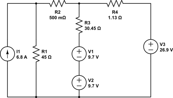
I have a problem where I must calculate the resistance required in R3 to have 1A flowing through the two 9.7V sources in the image below (i.e. Charging the batteries at a rate of 1A). I have simplified the initial circuit to what is shown here:
schematic

simulate this circuit – Schematic created using CircuitLab

Using Mesh Analysis from left to right I have the values:
I1 = 6.8A
I2 = 5.99637A
I3 = 5.54432A

So the branch of V1, V2 and R3 has a current of 0.45205A (confirmed by circuit simulator). I now need to make the current 1.

Using circuit simulators I have determined that I require the resistance of R3 to be approx. 13.16Ω to achieve 1A through that branch, but I cannot reason the maths to myself (and obviously I need to understand not just give a correct answer).

I've been thinking about it from an Ohms law perspective but I cannot seem to get it to add up. I know that I will = 1 for the branch, but I cannot figure out how to get V to calculate R. Using KVL around the circuit hasn't really helped me either.
I've reasoned for I to equal 1, then I2-I3 = 1 this will however also affect the relationship of I1 to I2. So I'm getting a bit tripped up on reasoning the problem.
Any help in the right direction would be appreciated.

\$\endgroup\$

4 Answers 4

1
\$\begingroup\$

You want to find the value of R3 that results in 1 A thru it.

Thevenin is your friend here. Keep reducing the power sources to Thevenin equivalents, and combine them. I1 and R1 are already a Norton source, so really easy to flip to Thevenin. Then add R2 to that Thevenin source. Now find the equivalent when that is connected to the Thevenin source of V3 and R4. Now you have a single Thevenin source driving the R3,V1,V2 string.

That Thevenin voltage minus V1 and V2 is what is across RThevenin and R3. By Ohm's law, find what RThevenin+R3 needs to be. The subtract RThevenin, and the result is R3.

\$\endgroup\$
0
\$\begingroup\$

You can do it this way (I find it easier to break into multiple steps):

Convert the subcircuit with I1 R1 R2 into its Thevenin equivalent. Do the same with the--- never mind, for V3 R4 it's already done...

Ok, now you should have one branch with a 306 V voltage source and 45.5 ohm resistance and the other, well you know. I am leaving the branch with the batteries and R3 alone. Now convert the two generator branches into a single voltage source with resistance. If you draw the circuit you will see how to compute the open circuit voltage: compute the current in the series, and then find the open circuit voltage by suitably adding/subtracting the voltage drop on one of the two resistor to the corresponding generator's voltage. The equivalent resistance is the parallel of the 45.5 and 1.13 ohm resistances; again if you draw the circuit and substitute the generators with shorts, you should be able to see that.

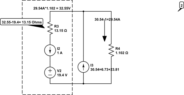
In the end, the equivalent Thevenin circuit that the batteries and R branch sees should come out as 33.66 V and 1.10 ohm.

At this point you are left with two facing voltage generators (33.66 and 19.4 V) with their resistances (1.10 ohm and R), one of which is to be determined to allow a certain I. For I = 1 A I get R = 13.16 ohm.

\$\endgroup\$
4
  • \$\begingroup\$ Thanks for your answer @Sredni Vashtar. It explains it very well, however I'm not sure on the "convert the two generator branches into a single voltage source with resistance". I can't follow this step. Would you able to explain how you get the 33.6V and 1.10ohm and then the two voltage generators 33.6v 19.4v figures. \$\endgroup\$
    – James
    Commented Sep 11, 2016 at 8:37
  • \$\begingroup\$ You have to draw the circuit. Then you'll see. See my edit, too. Also, I am assuming you are familiar with the Thevenin and Norton equivalent circuit determination. \$\endgroup\$ Commented Sep 11, 2016 at 8:39
  • \$\begingroup\$ Thanks Sredni. I am familiar with Thevenin circuits at a beginner level and I have been drawing and redrawing the circuits. I'm still stuck at the same point. My problem is if I consider V1,V2,R3 as the 'Load' and then find Vth (by setting the voltage sources as closed circuits). I then have R2 & R4 in series (0.5+1.13 = 1.63) and then that Req with R1 in parallel as 1/((1/1.63)+1/45)) = 1.573. So my Rth is 1.573. I then calculate the open circuit voltage as 306-26.9 (series voltages add?). These numbers come close to \$\endgroup\$
    – James
    Commented Sep 11, 2016 at 9:04
  • \$\begingroup\$ Actually I think I've figured it out. I did a mesh analysis of the two Thevenin circuits. -306+45i+1.13i+26.9=0, I=5.99A, 5.99 * 45.5 = 272.33661V drop across the resistor. 306-272.336 = 33.66V \$\endgroup\$
    – James
    Commented Sep 11, 2016 at 9:49
0
\$\begingroup\$

The voltage where the three resistors meet is easy to calculate, either 9.7 plus 9.7 plus or minus 1a x R3, depending on the current flow.

All the current going into that node sums up to zero.

\$\endgroup\$
0
\$\begingroup\$

The Norton equivalents lead to the same result as your Mesh Analysis

schematic

simulate this circuit – Schematic created using CircuitLab

schematic

simulate this circuit

schematic

simulate this circuit

\$\endgroup\$

Your Answer

By clicking “Post Your Answer”, you agree to our terms of service and acknowledge you have read our privacy policy.

Not the answer you're looking for? Browse other questions tagged or ask your own question.