1
\$\begingroup\$

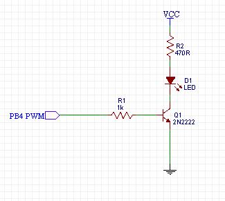
I have an ATTiny85 with a PWM output (freq. aprox. 1kHz). Connected to this pwm output pin is a NPN general purpose BJT (2N2222) with base resistor of 1k. A LED is in series with this transistor (before the collector). The LED has a current limiting resistor of 470R.

Everything seems to work pretty good, but if my PWM duty cycle is very low (< 30%), then something strange happens. Every few seconds the LED flashes/flickers. But it's not the well known PWM flickering. My flickering is very irregular (just every few seconds).

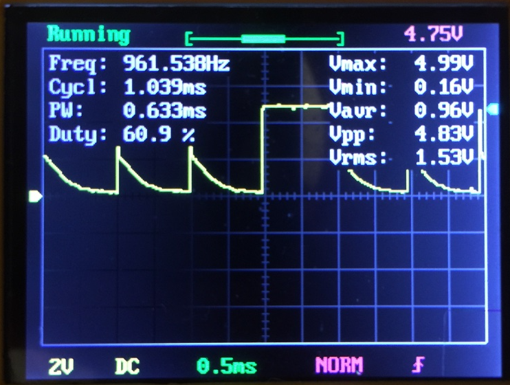
I used a oscilloscope and did some probing. The PWM output signal directly at the microcontroller pin was ok in my opinion. Then I checked the conductivity of the transistor, connecting my scope probes to the vcc and emitter of the transtistor. This gave me the following result (see picture).

osci

Am I correct, the the transistor is not properly switching off, and "skips one cycle"? This could be the reason, why the LED flickers?

Now the most important questions: Am I using the wrong transistor type - or should I switch to a mosfet-based solution? What would you suggest, to solve this issue?

Thank you very much. You help is greatly appreciated!

Here is the schematic: schematic

\$\endgroup\$
15
  • 1
    \$\begingroup\$ If that is a Vce your bjt is not switching on, not off. And it does turn on veeeery slowly. Please add Vbe to the scope (you have two probes don't you?) and snap a pic of your circuit. I suspect you swapped the transistor terminals. \$\endgroup\$ Commented Sep 21, 2016 at 16:49
  • 1
    \$\begingroup\$ When it comes to electronics, schematics are usually better than words to describe a circuit... Also, can you capture a trace showing the base drive voltage when that issue occurs? \$\endgroup\$
    – brhans
    Commented Sep 21, 2016 at 16:49
  • \$\begingroup\$ @brhans Sorry, I have added my schematic to my question above. \$\endgroup\$
    – J. Frôbes
    Commented Sep 21, 2016 at 17:06
  • \$\begingroup\$ BJTs just aren't that slow, nor could any I've seen account for that long, drawn-out decay. There is something on the driving end -- the PB4 end -- that is causing this, or else there is something seriously wrong elsewhere. One test to try is to use a different I/O pin and see if that helps any, or changes anything. But I've used 2N2222A BJTs for lots faster things. There's missing information here. \$\endgroup\$
    – jonk
    Commented Sep 21, 2016 at 17:21
  • 2
    \$\begingroup\$ @KyranF This is 1kHz, for gosh sake. It's not a situation requiring extra measures. There's something else going on. \$\endgroup\$
    – jonk
    Commented Sep 21, 2016 at 17:34

2 Answers 2

2
\$\begingroup\$

You will get confusing results if you measure Vce because the pullup is nonlinear (due to the LED). Try measuring the voltage across the 470 ohm resistor. Or parallel the LED with 1K and go back and measure Vce again.

I suspect your problem has nothing to do with the transistor and more to do with resetting the micro due to poor bypassing or something of that ilk.

\$\endgroup\$
4
  • \$\begingroup\$ Thanks for your comment, but for sure, the microcontroller is not resetting, I have verified this. \$\endgroup\$
    – J. Frôbes
    Commented Sep 21, 2016 at 17:36
  • \$\begingroup\$ Well, it could certainly be a firmware bug where you are overflowing a counter or whatever at low PWM frequency. The point is, I don't think the transistor is where you should be pointing the finger. \$\endgroup\$ Commented Sep 21, 2016 at 17:39
  • \$\begingroup\$ I'm using OC1B for pwm, I don't see any issue on the scope when I probbe the pwm output directly at PB4 \$\endgroup\$
    – J. Frôbes
    Commented Sep 21, 2016 at 17:48
  • \$\begingroup\$ well if it's only one pulse that's twice the length without change in amplitude you won't spot it as easily in the PWM signal. There's definitely current flowing to the base. \$\endgroup\$
    – Felix S
    Commented Sep 21, 2016 at 18:06
0
\$\begingroup\$

Could be the PWM output is not switching to ground, but going open(hi-impedance). And a related problem with r-m-w causing intermittant wrong output on pin.

At 6mA collector current, you need < 1mA base current. Increase base resistor to 4.7k.

Your pulse width looks very narrow. set a smaller ratio to test.

\$\endgroup\$

Your Answer

By clicking “Post Your Answer”, you agree to our terms of service and acknowledge you have read our privacy policy.

Not the answer you're looking for? Browse other questions tagged or ask your own question.