1
\$\begingroup\$

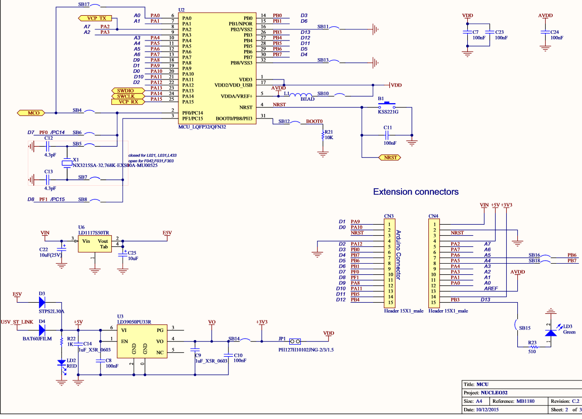
enter image description hereI got a new STM32F0 31 K6 nucleo board and I need to make a GSM UART interface on that board. I need to send an AT and receive an OK from the GSM board as a first step.I am able to transmit AT successfully But cannot receive anything. I am using IAR. I am using PA9 - TX and PA10 - RX. How to create a transmit and receive code using interrupts using this HAL library. I wrote code using interrupts and it's not giving a single character. This is my code

     int main(void)
{

  HAL_Init();
  /* Configure the system clock to 48 MHz */
  SystemClock_Config();
    /* Configure LED3 */
  BSP_LED_Init(LED3);
  UART_Init();
  BSP_LED_Off(LED3);
  if(HAL_UART_Transmit(&UartHandle, (uint8_t*)aTxBuffer, TXBUFFERSIZE,100)!= HAL_OK)
  {
    Error_Handler();
  }

    if(HAL_UART_Receive_IT(&UartHandle, (uint8_t *)aRxBuffer,6) != HAL_OK)
  {
    Error_Handler();
  }
   /*##-5- Wait for the end of the transfer ###################################*/   
  while (UartReady != SET)
  {
  } 
    /* Reset transmission flag */
  UartReady = RESET;
  /*if(HAL_UART_Transmit(&UartHandle, (uint8_t*)aRxBuffer, 6,1000)!= HAL_OK)
  {
    Error_Handler();
  }*/
  while (1)
  {
  }
}

IRQ handler

void USARTx_IRQHandler(void)
{
  HAL_UART_IRQHandler(&UartHandle);
}

Receive callback function

void  HAL_UART_RxCpltCallback(UART_HandleTypeDef *UartHandle)
{
  if(UartHandle->Instance == USARTx)
  {  
    /* Set transmission flag: transfer complete */
    UartReady = SET;
    BSP_LED_On(LED3); 
  }
}

And when I am debugging the code stuck at this point .

/*##-5- Wait for the end of the transfer ###################################*/   
  while (UartReady != SET)
  {
  } 

My actual application is to send an SMS to the GSM board using UART and collect the reply in a buffer and then parse it.First i need to make this interface And I cannot use DMA as there is no idea on how much data is received on this commuunication.

please help guys..

Regards, olivia

\$\endgroup\$
8
  • 2
    \$\begingroup\$ I recommend starting by putting up some minimal compilable code that doesn't do what you think it should do, along with any insights you've gotten from attempts at debugging. \$\endgroup\$ Commented Nov 1, 2016 at 12:39
  • 1
    \$\begingroup\$ Please do the following... Read this: electronics.stackexchange.com/help/how-to-ask Ask a specific question, and provide all details relating to your question. A good question doesn't need clarification. What GSM interface? What communication bus? SPI I2C or RS232 (to name a few). These types of questions shouldn't have to be asked. \$\endgroup\$
    – Voltage Spike
    Commented Nov 1, 2016 at 16:31
  • \$\begingroup\$ @laptop2d It's UART according to the title. But it is unclear as it should have been included in the question body. \$\endgroup\$ Commented Nov 1, 2016 at 20:08
  • 2
    \$\begingroup\$ @OliviaChristy If you have a code which does not work, you should add that into the question as well. And a schematic maybe, make sure you did not mixed the RX-TX lines. \$\endgroup\$ Commented Nov 1, 2016 at 20:08
  • 1
    \$\begingroup\$ What is the flow control config regarding the GSM module? Also I am not interested in the Nucleo board's schematic, I am intetested in your schematic how did you connected the GSM module with the Nucleo. Maybe you should try to send and receive inside the main, multiple times. Basically your code seems to be fine (correct callback and Interrupt handler) but the hell knows what your GSM module expect as you still not added a datasheet. \$\endgroup\$ Commented Nov 4, 2016 at 8:35

3 Answers 3

3
\$\begingroup\$

A basic UART initialization with interrupts using HAL looks something like the one below. I do not want to descirbe the parameters as they are quite obvious. It is an actual pins configuration and the UART peripheral configuration. HAL_UART_MspInit is called by HAL_UART_Init, to use it you only need to call MX_USART1_UART_Init.

#include "stm32f0xx_hal.h"

UART_HandleTypeDef huart1;

void MX_USART1_UART_Init(void)
{
  huart1.Instance = USART1;
  huart1.Init.BaudRate = 115200;
  huart1.Init.WordLength = UART_WORDLENGTH_8B;
  huart1.Init.StopBits = UART_STOPBITS_1;
  huart1.Init.Parity = UART_PARITY_NONE;
  huart1.Init.Mode = UART_MODE_TX_RX;
  huart1.Init.HwFlowCtl = UART_HWCONTROL_NONE;
  huart1.Init.OverSampling = UART_OVERSAMPLING_16;
  huart1.Init.OneBitSampling = UART_ONEBIT_SAMPLING_DISABLED;
  huart1.AdvancedInit.AdvFeatureInit = UART_ADVFEATURE_NO_INIT;
  HAL_UART_Init(&huart1);
}

void HAL_UART_MspInit(UART_HandleTypeDef* huart)
{
  GPIO_InitTypeDef GPIO_InitStruct;
  if(huart->Instance==USART1)
  {
    __USART1_CLK_ENABLE();

    /**USART1 GPIO Configuration    
    PA2     ------> USART1_TX
    PA3     ------> USART1_RX 
    */
    GPIO_InitStruct.Pin = GPIO_PIN_2|GPIO_PIN_3;
    GPIO_InitStruct.Mode = GPIO_MODE_AF_PP;
    GPIO_InitStruct.Pull = GPIO_PULLUP;
    GPIO_InitStruct.Speed = GPIO_SPEED_HIGH;
    GPIO_InitStruct.Alternate = GPIO_AF1_USART1;
    HAL_GPIO_Init(GPIOA, &GPIO_InitStruct);

    HAL_NVIC_SetPriority(USART1_IRQn, 0, 0);       
    HAL_NVIC_EnableIRQ(USART1_IRQn);               // Enable Interrupt
  }
}

The interrupt handling is the following:

void USART1_IRQHandler()
{
  HAL_UART_IRQHandler(&huart1);
}

This is the actual ISR, and HAL_UART_IRQHandler(&huart1) is a HAL definied handler function. It checks which interrupt source flag has been set, calls a callback or wait for more byte to be received and clears the interrupt flags.

In case of RX interrupts this handler counts the received bytes and when the desired amount is received calls this callback function:

void HAL_UART_RxCpltCallback(UART_HandleTypeDef *huart)
{
  if (huart->Instance == USART1)
  {
    // Your buffer is full with your data process it here or set a flag
  }
}

The callback has a weak declaration, you have to implement it.

Now about usage. To send, the following HAL function can be used, this is the simplest:

HAL_UART_Transmit(&huart1, (uint8_t*)"AT\r", 3, 0xFFFFFF)

To receive with interrupt one must use the following function:

HAL_UART_Receive_IT(&huart1, uint8_t *pData, uint16_t size)

where pData is a pointer to the receive buffer and size is the number of bytes you are expecting. The HAL_UART_IRQHandler(&huart1) will call the callback if the number of received bytes equal to size.

All of this can be generated by using STM32CubeMX code generator, except the callbacks, those are not generated.


The GSM module probably has echo mode enabled by default, so to AT\r it will respond with \r\nAT\r\n\r\nOK\r\n, 12 bytes should be waited.

Echo mode can be disabled by ATE0 command and saved as default with the AT&W command. From that the answer will be \r\nOK\r\n to the AT\r.

\$\endgroup\$
0
0
\$\begingroup\$

I recently faced similar problem with my LTE module. It turns out that lots of such modules have Hardware flow control enabled by default. You can use HW flow control at your end as well or simply ground modules's CTS pin.

Also for some reason in my case the labelling for RX/TX and RTS/CTS was reversed. So i the above soluton did not work out you can try with swapped connections.

\$\endgroup\$
0
\$\begingroup\$

Thank you guys for the discussion! I faced the similar problem. In my case I enabled interrupts (NVIC_EnableIRQ), wrote HAL_UART_RxCpltCallback() and HAL_UART_Receive_IT() call.

But I missed this:

void USART1_IRQHandler() { HAL_UART_IRQHandler(&huart1); }

Without the handler above the interrupt can't be catched by HAL_UART_RxCpltCallback() and the app. enters an endless loop, as it sees no interrupt handler.

\$\endgroup\$

Your Answer

By clicking “Post Your Answer”, you agree to our terms of service and acknowledge you have read our privacy policy.

Not the answer you're looking for? Browse other questions tagged or ask your own question.